TM-9-2920-258-30-P - Page 13 of 76
TM 9-2920-258-30&P
CHAPTER 3
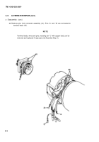
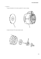
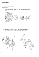
ALTERNATOR REPAIR
3-1
PRINCIPLES OF OPERATION
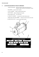
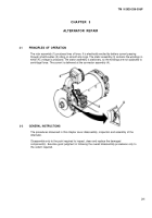
The rotor assembly (1) produces lines of force. It is electrically excited by battery current passing
through small brushes (2) riding on smooth slip rings. The stator assembly (3) contains the windings in
which AC voltage is produced. The stator assembly is stationary, so the windings are not subjected to
centrifugal force. The current is delivered at the connector assembly (4).
3-2
GENERAL INSTRUCTIONS
The procedures discussed in this chapter cover disassembly, inspection and assembly of the
Alternator.
Disassemble only to the point required to inspect, clean and replace the damaged
component(s). Exercise good judgment in following the overall disassembly procedures only to
the extent required.
3-1
Back to Top

