TM-9-6920-430-14 - Page 156 of 180
TM 9-6920-430-14
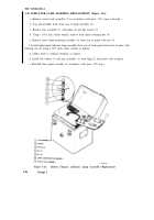
3-30. INDICATOR LAMP ASSEMBLY REPLACEMENT (Figure 3-16).
a. Remove circuit card assembly (7) in accordance with para. 3-28, steps
a
through
c.
b. Tag and unsolder leads from rear of lamp assembly (6).
c. Remove lens assembly (1) with lamp (2) and flat washer (3).
d. Using a 9/16 inch socket wrench, remove front panel retaining nut (4).
e. Remove lower lamp mounting assembly (6) from rear of panel with nut (5).
f. Install replacement indicator lamp assembly from rear of front panel and secure in place with
retaining nut (4) using a 9/16 inch socket wrench to tighten.
g. Solder leads to original terminals as tagged.
h. Install flat washer (3) and lens assembly (1) with lamp (2) from front side of panel.
i. Reinstall front panel assembly in accordance with para. 3-28 step j.
Figure 3-16.
Battery Charger, Indicator Lamp Assembly—Replacement
3-86
Change 1
Back to Top


