TM-9-6920-430-14 - Page 150 of 180
TM 9-6920-430-14
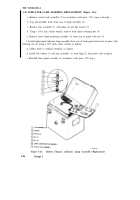
3-26.1 RELIEF VALVE REPLACEMENT PROCEDURE (Figure 3-12.1).
a. Remove housing enclosure in accordance with paragraph 3-18, steps a and b.
b. Using a 7/16-inch wrench, remove support bracket retaining screws (6) and bracket
assembly (1) form relief valve (2).
c. Remove both the filter (4) and high pressure input lines (5) from the relief valve tee
connector (3) using a 9/16-inch wrench.
d. Remove relief valve exhaust line (7) from relief valve coupling adapter (8) by
securing coupling in place with a 1-inch open end wrench and rotating connector
counterclockwise using a 5/8-inch open end wrench.
e. Remove tee connector (3) from relief valve assembly (2) and retain.
f. Remove relief valve assembly.
g. Install replacement relief valve in the reverse order of removal described in steps b
through f.
h. Perform proof pressure test in accordance with Section IV.
3-26.2 SOLENOID VALVE REPLACEMENT PROCEDURE (figure 3-12.1).
a. Remove housing enclosure in accordance with paragraph 3-18, steps a and b.
b. Remove inlet exhaust line (7) input to solenoid assembly (11) using a 5/8-inch open
end wrench.
c. Using a 7/16-inch wrench, remove bracket retaining screws (14) and bracket
assembly (12) from solenoid valve (10) and retain.
d. Remove screws (9) and cover plate (10) from TB1 function box (15) and disconnect
solenoid lead-in wires from terminals 1 and 2 on TB1.
e. Install replacement solenoid valve in the reverse order of removal described in steps
a through h.
f. Perform proof pressure test in accordance with Section IV.
3-82.6
Change 3
Back to Top


