TM-9-6920-430-14 - Page 148 of 180
TM 9-6920-430-14
3-26. INLET/OUTLET
a.
Disconnect the
b.
Vent system in
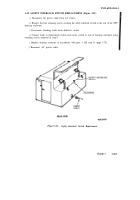
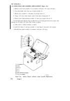
SHUTOFF OR BLEED VALVE REPLACEMENT. (Figure 3-2.)
power cable from AC source.
accordance with para. 3-16, steps a through c.
c.
Lift the trainer cover (1) at the rear of the GPU and open the rear access door (2) to
gain access to either the INLET SHUTOFF, INLET BLEED, OUTLET SHUTOFF, or
OUTLET BLEED valve assemblies (3).
d.
Using a 9/16 inch open end wrench, loosen the coupling nuts (4) located on both
sides of the valve assembly (only one side of the bleed valve) to be removed.
e.
Remove the seal cap (5) from the valve knob (6) using a small thin blade
screwdriver.
f.
Remove the knob retaining nut and washer (7) from the valve shaft using a 5/ 16 inch
socket wrench and pull knob forward to remove from shaft.
g.
Remove the front panel locking nut (8) using a 1-1/8 inch open end wrench.
h.
Remove coupling nuts (4) loosened in step e and remove valve from rear of panel by
tilting valve downward and out of its mounting hole.
h.i.
Remove elbow (9) from old valve (3) and install on replacement valve using
anti-seize tape (Item No. 14, Appendix E).
i.
Install replacement valve in mounting hole from rear of panel and attach coupling
nuts (4).
j.
Install front panel locking nut (8) and secure in place using a 1-1/8 inch open end
wrench.
k.
Tighten coupling nut(s) using a 9/16 inch open end wrench.
l.
Install knob (6) and secure in place with washer and nut (7) using a 5/16 inch socket
wrench.
m.
Install knob seal cap (5) by centering over indent hole of knob and pressing in place.
n.
Connect power cable to AC source and purge system as described in para.
3-18h.
3-82.4
Change 6
Back to Top


