TM-9-6920-430-14 - Page 154 of 180
TM 9-6920-430-14
3-28. CIRCUIT CARD ASSEMBLY REPLACEMENT (Figure 3-14).
a.
Disconnect unit from AC power source.
b.
Loosen the 10 front panel retaining screws (1) and lift assembly from cabinet.
c.
Lay panel assembly face down on cabinet.
d.
Remove rear circuit card assembly in accordance with para. 3-29 steps h and c.
e.
Remove the 10 circuit board retaining screws (5), spacers (7), washers (8), lockwashers (9) and
nuts (10) securing mounting brackets (3) to the rear of the circuit card assembly and retain hardware.
f.
Disconnect connectors J1 (11) and J2 (12) from circuit card.
g.
Install mounting brackets (3) to the rear of replacement circuit card by reinstalling the 10
circuit board retaining screws (5), washers (6), spacers (7), washers (8), lockwashers (9) and nuts (10).
h.
Connect J1 (11) and J2 (12) connectors to circuit card assembly.
i.
Install reassembled circuit card assembly in accordance with para. 3-29 step h.
j.
Reinstall front panel in cabinet and secure in place by tightening the 10 front panel retaining
screws (1).
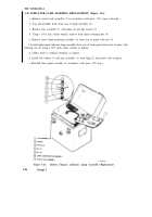
Figure 3-14. Battery Charger Circuit Card “Assembly Replacement
3-84
Change 1
Back to Top


