MWO-5-2350-262-35-3 - Page 37 of 45
MWO 5-2350-262-35-3
2-31
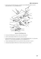
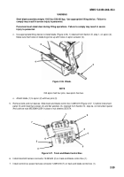
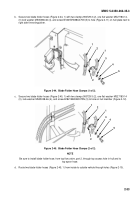
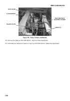
10. Remove four screws (Figure 2-40, 6) on ejector panel (1) and move panel downward, retaining screws for future
use.
Figure 2-40.
Ejector Panel.
11. Remove control harness lead #450 (Figure 2-40, 4) from bilge pump switch (7) lead (5).
12. Remove bilge light lead #450 (2) from bilge pump switch (7) lead (3).
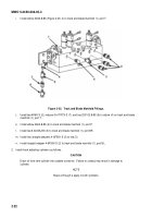
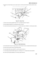
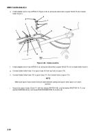
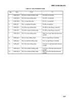
13. Connect hull wiring harness leads (Figure 2-41, 4) to blade folder harness 12491607 (5), matching lead numbers.
Figure 2-41.
Blade Folder Harness.
14. Route blade folder harness (5) through opening on lower left side into driver’s compartment behind ejector panel.
15. Route control box power harness (2) behind ejector panel.
16. Connect blade folder harness lead #514 to control box power harness (2).
17. Connect bilge pump light lead #450 (Figure 2-40, 2 and Figure 2-41, 1) to blade folder harness lead #515.
18. Connect control harness lead #450 (3) to control box power harness (2).
#515
4
6
5
4
3
3
#514
7
5
1
#450
2
1
2
Back to Top

