MWO-9-2300-378-34-2 - Page 40 of 92
MWO 9-2300-378-34-2
Section III. Hull Wiring Instructions for M60A3 and M60A1 (RSE) Vehicles
NOTE
Figures 33, 34, 35, 36 and 37 shown for reference and
clarity.
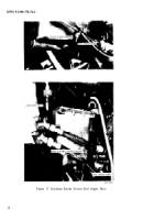
(1) Inside driver’s compartment, remove and discard four screws MS90726-6 and
lockwashers MS35338-44 securing gage indicator panel to its mounting bracket (figure 27).
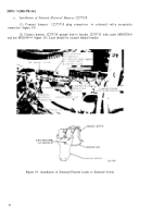
(2) Route switch plug connector end of harries assembly 12270526 along existing
harness behind gage indicator panel and secure with existing clamps MS90350-23, as shown in
figure 28, view A.
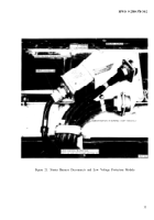
(3) Connect
receptacle connector
mounting bracket with
For
and
harness 12270526 plug connector to smoke generator switch assembly
and attach switch bracket along with gage indicator panel-to-panel
four screws MS90726-9 and lockwashers MS35333-40 (figure 29).
NOTE
vehicles without M-9 bulldozer, perform steps 1, 2,
3, then steps 14 thru 25. For vehicles with M-9
bulldozer, perform steps 4 thru 25.
Figure 27. Removing Gage Indicator Panel
38
Back to Top


