MWO-9-2300-378-34-2 - Page 33 of 92
MWO 9-2300-378-34-2
NOTE
When installing lead loop clamps, insure lead remains in
rubber of loop clamp and has not been pinched. Clamps
should not be twisted when tightened down.
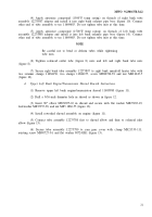
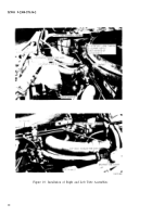
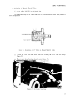
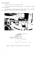
(3) Secure left bank tube assembly 12275808 and solenoid positive lead to left bank
manifold heater tube with two retainer clamps 1168156, two clamps 11684157, lead clamp
MS21333-108, screw MS90726-39, and nut MS21045-5 (figure 19).
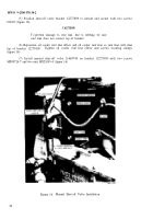
(4) Secure solenoid positive lead to intermediate left bank transmission shroud with
clamp MS21333-108 and existing screw 7414584 (figure 19).
(5) Secure positive lead to engine oil cooler support frame with clamp MS21333-108
and existing screw 7414584 (figure 19).
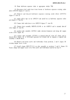
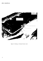
(6) Remove and discard existing screw (apposition 9, figures l8 and 20).
(7) Position clamp MS21333-111 on tube assembly 12275811 and clamp MS21333-108
on solenoid positive lead and secure clamps to engine access cover with screw MS90726-32 and
lockwasher MS35335-34 (figure 20).
(8) Remove and retain existing screw at position 7, figures 18 and 20.
(9) position clamp MS21333-lo8 on solenoid positive lead and secure clamp at
posit ion 7 (figure 20) with screw removed in step 8.
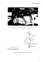
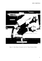
(10) Remove and retain securing hardware and remove starter harness retaining strap
11684276-2 and low voltage protection module harness clamp MS21333-125 (figure 21).
(11) Disconnect cable connector from low voltage protection module (figure 20.
(12) Remove five screws and lock washers securing bracket 12254374 to engine access
cover (figure 21). Position bracket and cables aside.
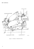
(13) Place clamp MS21333-111 on tube assembly 12275811 at position 4 (figure 18
and 22). It may be necessary to loosen clamps at position 2 and 6 (figure 18) and install clamp
at position 4.
NOTE
Be sure tabs of clamp MS21333-111 at position 4 are
under bracket 12254374 when installing securing hardware.
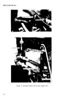
(14) Replace bracket 12254374 onto engine access cover and secure with four of the
screws and washer removed in step 12, (figure 22). Do not install screw and washer at positon 5
at this time, (figures 18 and 22).
(15) ,Remove four screws, nuts,
and lockwashers securing positive starter harness
receptacle to bracket 12254374 (figure 22).
31
Back to Top

