MWO-9-2300-378-34-2 - Page 23 of 92
MWO 9-2300-378-34-2
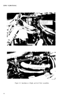
(4) Apply antiseize compound (1500°F temp rating) on threads of right bank tube
assembly 12275807 adapter and install it into right bank exhaust pipe boss (figure 10). Connect
other end of tube assembly to tee 11669685. Do not tighten tube nuts at this time.
(5) Apply antiseize compound (1500°F temp rating) on threads of left bank tube
assembly 12275808 adapter and install it into left bank exhause pipe boss (figure 10). Connect
other end of tube assembly to tee 11669685. Do not tighten tube nuts at this time.
NOTE
Be careful not to bend or deform tubes while tightening
tube nuts.
(6) Tighten solenoid outlet tube (figure 8) nuts and left and right bank tube nuts
(figure 8).
(7) Secure right bank tube assembly 12275807 to right bank manifold heater tube with
two retainer clamps 11684156, two clamps 11684157, screw MS90726-39 and nut MS21045-5
(figure 10).
d.
Upper Left Bank Engine/Transmission Shroud Rework Instructions.
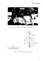
(1) Remove upper left bank engine/transmission shroud 11683980 (figure 11).
(2) Drill a 9/16-inch diameter hole in shroud as shown in figure 12.
(3) Insert 90° elbow MS51855-10 in shroud and secure with flat washer MS27183-19,
lockwasher MS35355-38, and nut MS5 1860-55 (figure 12).
(4) Install reworked shroud assembly on engine (figure 11).
(5) Connect tube assembly 12275780 first to shroud elbow and then to solenoid inlet
elbow (figure 13).
(6) Secure tube assembly 12275780 to cam gear cover with clamp MS21333-111,
existing screw MS90727-34, and flat washer 907241K1 (figure 13).
21
Back to Top

