MWO-9-2300-378-34-2 - Page 43 of 92
MWO 9-2300-378-34-2
NOTE
For vehicles equipped with the M-9 bulldozer, the smoke
generator switch assembly will be installed along with the
hydraulic pump control panel on top of the gage indicator
panel.
In order to do this, the hydraulic pump bracket
must be reworked.
The following steps 4 thru 13 will
detail this procedure.
(4) Inside driver’s compartment,
remove and discard four screws MS907 27-7 and
lockwashers MS35333-40 securing hydraulic pump control panel and gage indicator panel to
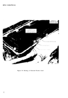
their mounting bracket (figure 30).
(5) Remove and retain hardware securing circuit breaker to hydraulic pump control
bracket. Leave electrical leads connected and remove circuit breaker (figure 3O).
(6) Remove hydraulic pump indicator light lens (figure 30). Remove and retain
hardware securing indicator light assembly to hydraulic pump control bracket. Leave electrical
lead connected and remove indicator light assembly (figure 30).
(7) Remove and retain hardware securing hydraul.ic switch to hydraulic pump control
bracket. Leave electrical leads connected and remove switch (figure 30).
(8) Rework hydraulic pump bracket as shown in figure 31.
(9) Reinstall hydraulic pump
switch on reworked bracket with two screws
MS35206-245 and lockwashers MS35333-38 (figure 30).
(10) Reinstall indicator light on reworked bracket with two screws MS35206-245 and
lockwashers MS35333-38 and screw lens back on (figure 30).
(11) Reinstall circuit breaker on reworked bracket with two screws MS35206-245 and
lockwashers MS35333-38 (figure 30).
(12) Route engine smoke harness 12270526 (switch plug connector end) along existing
harness behind gage indicator panel and secure with existing clamps MS90350-23 as shown in
figure 28, view A.
(13) Connect harness 12270526 plug connector to smoke generator switch assembly
receptacle connector and attach smoke switch bracket and hydraulic pump switch bracket along
with gage indicator panel-to-panel mounting bracket with four screws MS90726-9 and
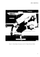
lockwashers MS35333-40 (figure 32).
(14) Route smoke harness 12270526 back along existing harnesses to the air cleaner
blower motor relay (figure 28, view B and C) and route single lead Of smoke harness Positive
lead up to bulkhead disconnects (figure 28, view D). Do not secure harness at this time.
(15) Disconnect blower motor relay plug connector and connect one end of smoke
harness 12270526 to the relay and the other end to the connector as shown in figure 28, view C.
(16) Secure smoke harries along existing harness from the switch to the relay and
secure with the existing retaining straps as shown in figure 28. Additional harness retaining
strap 10905840 is supplied in kit if needed.
41
Back to Top


