SMI-9-2320-387-14P-1 - Page 104 of 671
10-57.1. C-PILLAR REINFORCEMENT BRACKETS INSTALLATION
This task covers:
Installation
INITIAL SETUP:
Applicable Models
M1151, M1152
Tools
General mechanic’s tool kit:
automotive (Appendix B, Item 1)
Materials/Parts
Two brackets (Appendix D, Fig. D-116)
Two locknuts (Appendix G, Item 101.6)
Eight rivets (Appendix G, Item 269.1)
Manual Reference
TM 9-2320-387-10
TM 9-2320-387-24P
TM 43-0139
Equipment Condition
Soft top removed as required (TM 9-2320-387-10).
SMI 9-2320-387-14&P-1
10-96.2
Change 4
NOTE
• The following procedure can be performed to prevent fatigue
cracking of the C-pillar mount brackets. Installation is at
commander’s discretion.
• For instructions on replacement of rivets, refer to para. 10-56.
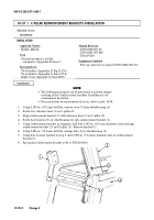
1.
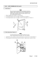
Using 0.187-in. (4.75 mm) drill bit, remove rivet (5) from wheelhousing (4).
2.
Scribe two reference lines (3) on C-pillar (2).
3.
Align reinforcement bracket (1) with reference lines (3) on C-pillar (2).
4.
Scribe hole location (5) on wheelhousing (4) onto reinforcement bracket (1).
5.
Using reinforcement bracket as template, drill four 0.187-in. (4.75 mm) diameter holes through
reinforcement bracket (1) and C-pillar (2). Remove bracket (1).
6.
Using 0.281-in. (7.14 mm) drill bit, enlarge hole (5) in wheelhousing (4).
7.
Using hole location marked in step 4, drill 0.281-in. (7.14 mm) diameter hole in reinforcement
bracket (1).
8.
Spot paint reinforcement bracket (refer to TM 43-0139).
Installation
1
2
3
4
~
5
Back to Top

