TB-9-2300-378-14 - Page 180 of 296
TB 9-2300-378-14
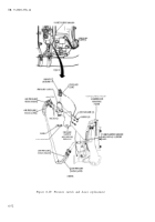
(2) Installation
(a)
(b)
(c)
(d)
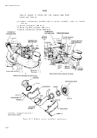
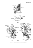
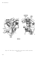
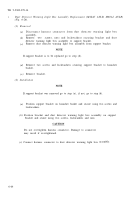
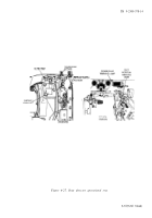
Connect connector 509B of replacement hull intermediate lead assembly to
short lead of dust detector warning light harness assembly (view B).
Route socket contact end of replacement hull intermediate lead assembly
beneath cable retaining straps from dust detector warning light box (view B)
to starter cable bulkhead connector (view A).
At bulkhead connector (view A) push lead assembly socket contact 509B
through retaining nut and install contact in position “C” of starter cable plug
assembly (view A).
Assemble retaining nut to starter cable plug assembly and connect plug
—
assembly to bulkhead connector.
(e)
Secure lead assembly to harness bundle with tie wrap as required.
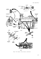
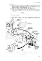
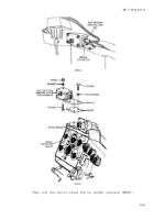
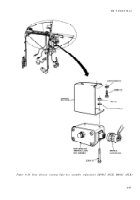
f. Dust Detector Warning Light Wiring Harness Assembly Replacement (Fig. 6-23).
(1) Removal
(a)
Disconnect three battery ground cable assemblies from battery terminals.
(b)
Disconnect four lead connectors connecting dust detector warning light
wiring harness to front master harness assembly and powerplant warning light
harness.
(c)
Remove screw and lockwasher securing dust detector warning light ground
lead alongside of gage indicator panel.
(d)
Disconnect dust detector warning light wiring harness short lead 509B from
hull intermediate lead assembly 509B.
(e)
Disconnect harness connector from dust detector warning light box.
(f)
Remove dust detector warning light wiring harness from vehicle.
(2) Installation
(a)
(b)
(c)
(d)
(e)
(f)
Connect harness connector to dust detector warning light box.
Connect dust detector warning light short lead 509B to hull intermediate
lead assembly.
Secure dust detector warning light ground lead with screw and lockwasher
alongside driver’s gage indicator panel.
Connect dust detector warning light wiring harness lead
509L to lead connectors 509A and 509L of powerplant
harness and front master harness assembly.
Connect three ground cables to batteries.
Press test lamp on dust detector warning light box
connectors 509A and
warning light wiring
to insure circuit is
functioning.
g.
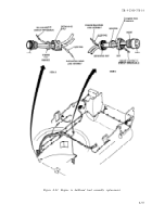
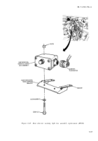
Dust Detector Warning Light Box Assembly Replacement (M60A3) (Fig. 6-24).
(1) Removal
(a)
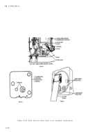
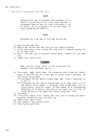
Disconnect harness connector from dust detector warning light box (view A).
CAUTION
Support gage indicator panel mounting bracket when
removing light box mounting screws. Gage indicator panel
mounting bracket is secured using the same screws and may
fall.
(b)
Remove four screws and lockwashers securing bracket, dust detector warning
light box assembly, and spacer to switch bracket on gage indicator panel
(view B).
(c)
Remove two screws, nuts, and lockwashers securing dust detector warning
light box assembly to bracket. Separate box assembly and bracket.
6-58
Back to Top

