TB-9-2320-279-13-P-2 - Page 112 of 460
TB 9-2320-279-13&P-2
UPPER BRUSH GUARD REPLACEMENT - CONTINUED
0018 00
0018 00-4
INSTALLATION - CONTINUED
4.
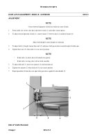
Use lifting device to position upper brush guard (15) over threaded studs, upper brush guard shim (18), and lower brush
guard, with up arrow
⇑
facing installer.
WARNING
Use caution when using adhesives and sealants. Prolonged inhalation of vapors can cause lung irritation.
Contact with skin can cause dermatitis. Wear gloves and safety goggles and use product in a well-ventilated
area away from open flame. If ingested, keep individual calm and seek medical attention. DO NOT induce
vomiting. If contact with skin or eyes is made, flush thoroughly with water. Dispose of cleanup rags IAW
local policy and ordinances. Failure to follow this warning may cause injury to personnel.
NOTE
•
Do not install bolts in headlight
bracket holes.
•
Threaded studs are removed as bolts are installed.
5.
Apply thread adhesive to bolts (16). Install six washers (17) and bolts (16) in top row of upper brush guard (15). Hand
tighten bolts.
6.
Check alignment of upper brush guard (15). Adjust as necessary.
7.
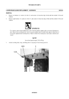
Install eight washers (11), bolts (12), washers (13), and new locknuts (14) in bottom row of upper brush guard (15).
Tighten locknuts to 35 lb-ft (47 Nm).
8.
Tighten four bolts (16) in upper brush guard (15) to 35 lb-ft (47 Nm).
WARNING
Use extreme caution when handling heavy parts. Provide adequate support and use assistance during proce-
dure. Failure to follow this warning may cause injury to personnel.
NOTE
Upper brush guard cover weighs 26 lb (12 kg).
9.
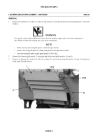
Install upper brush guard cover (5) with three washers (4), bolts (1), washers (2), and new locknuts (3).
10.
Install blackout light and bracket assembly (6), washer (8), bolt (7), washer (10) and new locknut (9).
Back to Top


