TB-9-2320-279-13-P-3 - Page 379 of 396
TB 9-2320-279-13&P
0040
0040-129
9.
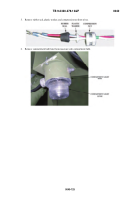
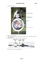
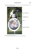
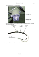
Route black wire and white wire through compression fitting on driver side compartment light base,
and install compression nut on compression nut base.
A2 model shown; previous models similar.
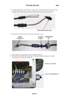
10. Connect black wire with blade connector to existing blade connector.
If connectors will not mate,
remove both blade connectors and connect black wires with butt splice connector, cover with heat-
shrink.
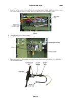
11. Install white wire ring terminal ground connector on screw.
Back to Top


