TB-9-2320-280-35-12 - Page 131 of 162
TB 9-2320-280-35-12
5-103
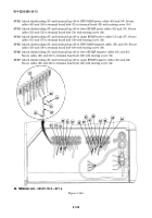
47-25.
Attach shrink tubing (35) and terminal lug (33) to master kill switch positive power cable (36).
Secure cable (36) to terminal board hole (37) in terminal board (32) with existing screw (34).
47-26.
Attach shrink tubing (35) and terminal lug (33) to Prosine inverter positive power cable (39). Secure
cable (39) to terminal board hole (38) with existing screw (34).
47-27.
Attach shrink tubing (35) and terminal lug (33) to shunt-to-terminal negative cable (41). Secure
cable (41) to terminal board hole (40) with existing screw (34).
47-28.
Attach shrink tubing (35) and terminal lug (33) to rear battery negative cable (43). Secure cable (43)
to shunt (47) with existing screw (42).
47-29.
Attach shrink tubing (35) and terminal lug (33) to Prosine inverter negative cable (44). Secure
cable (44) to shunt (47) with existing screw (45).
47-30.
Attach shrink tubing (35) and terminal lug (33) to shunt-to-terminal negative cable (41). Secure
cable (41) to shunt (47) with existing screw (45).
47-31.
Attach shrink tubing (35) and terminal lug (33) to shunt negative cable (46). Secure cable (46) to
shunt (47) with existing screw (45).
38
39
40
41
42
43
44
45
46
47
32
33
34
35
36
37
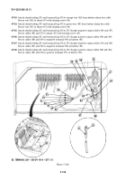
Figure 5-143.
33. TERMINAL LUG – CRS-DY-1406 – QTY. 7
35. SHRINK TUBE – MS23053/4-302-0 – QTY. A/R
34
34
Back to Top


