TB-9-2320-302-13-P-3 - Page 135 of 240
TB 9-2320-302-13&P-3
RECEIVER/DRYER REPLACEMENT - CONTINUED
0019 00
0019 00-3/(0019 00-4 Blank)
REMOVAL - CONTINUED
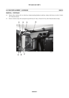
6.
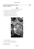
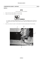
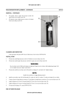
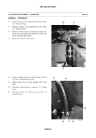
If required, remove engine fan pressure switch (12)
(gray) from receiver/dryer unit (10).
7.
If required, remove high pressure switch (13) (black)
from receiver/dryer unit (10).
CLEANING AND INSPECTION
Clean and inspect all parts IAW
General Maintenance Instructions
(WP 0014 00).
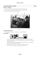
INSTALLATION
1.
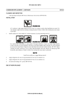
If removed, install high pressure switch (13) (black) on receiver/dryer unit (10).
2.
If removed, install engine fan pressure switch (12) (gray) on receiver/dryer unit (10).
WARNING
Receiver/dryer unit will fall until clamps are tightened. Support receiver/dryer while tightening clamps. Fail-
ure to comply may cause injury to personnel.
3.
If removed, install receiver/dryer unit (10) inside two clamps (11) on bracket (9). Tighten clamps.
NOTE
Install wires and hoses as tagged during removal.
4.
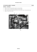
Install receiver/dryer unit (10) with bracket (9), washer (6), bolt (5), washer (7), and new locknut (8) on vehicle.
5.
Connect chassis wiring harness connector (3) and chassis wiring harness connector (2) to receiver/dryer unit (10).
6.
Apply refrigerant oil to new O-ring and install A/C hose (4) on receiver/dryer unit (10).
7.
Apply refrigerant oil to new O-ring and install A/C hose (1) on receiver/dryer unit (10).
8.
Evacuate and recharge A/C system (WP 0015 00).
END OF WORK PACKAGE
449-078
12
13
10
Back to Top

