TB-9-2320-387-35-4 - Page 37 of 109
5-21
TB 9-2320-387-35-4
8-9.
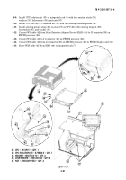
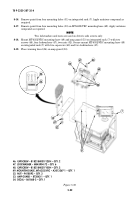
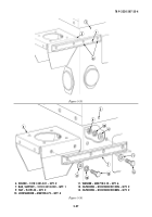
Install CPU isolation kit (33) on integrated rack (7) with four existing studs (19),
washers (35), lockwashers (36), and nuts (37).
8-10.
Install CPU (26) on CPU isolation kit (33) with two existing fastener guards (34).
8-11.
Install existing ground strap (28) on stud (27) on CPU (26) with existing wingnut (29),
lockwasher (30), and washer (31).
8-12.
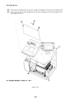
Connect W3 cable (42) from Serial Interface Adapter Device (SIAD) (44) to J3 connector (39) on
FBCB2 processor (26).
8-13.
Connect W1 cable (41) to J1 connector (40) on FBCB2 processor (26).
8-14.
Connect W2 cable (43) from J4 connector (38) on FBCB2 processor (26) to FBCB2 display unit (32).
8-15.
Route W3N cable (45) from SIAD (44) to integrated rack (7).
Figure 5-29.
33
7
34
34
28
36
35
37
26
26
27
28
29
31
30
26. CPU – 881292-1 – QTY. 1
33. CPU ISOLATION KIT – 872826-2 – QTY. 1
35. WASHER – MS27183-10 – QTY. 4
36. LOCKWASHER – MS35338-44 – QTY. 4
37. NUT – MS35649-2252 – QTY. 4
45
44
26
38
39
40
41
42
43
32
19
Back to Top

