TB-9-2320-387-35-4 - Page 31 of 109
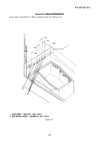
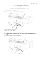
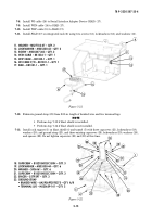
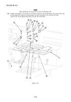
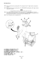
18. CAPSCREW – B1821BH025C150N – QTY. 3
19. LOCKWASHER – MS35338-44 – QTY. 6
20. WASHER – 2436161 – QTY. 6
21. CAPSCREW – B1821BH025C100N – QTY. 3
22. SPACER – 5579297 – QTY. 3
23. GROUND STRAP
• BRAIDED WIRE – AA59569F30T0375 – QTY. A/R
• TERMINAL LUG – MS20659-141 – QTY. 2
5-15
TB 9-2320-387-35-4
7-8.
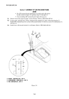
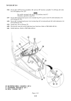
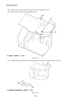
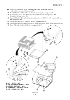
Install W3 cable (16) to Serial Interface Adapter Device (SIAD) (17).
7-9.
Install W3N cable (14) to SIAD (17).
7-10.
Install W3P cable (15) to SIAD (17).
7-11.
Install SIAD (17) on integrated rack (6) using two screws (13), lockwashers (12), and washers (11).
Figure 5-21.
12
11
13
14
15
16
11. WASHER – MS27183-47 – QTY. 2
12. LOCKWASHER – MS35338-43 – QTY. 2
13. SCREW – MS35207-263 – QTY. 2
14. W3N CABLE – 881336-1 – QTY. 1
15. W3P CABLE – 881335-1 – QTY. 1
16. W3 CABLE P/O – 881331-1 – QTY. 1
17. SIAD – 881331-1 – QTY. 1
7-12.
Fabricate ground strap (23) from 8.00-in. length of braided wire and two terminal lugs.
NOTE
• Perform step 7-13 if blast shield is installed.
• Perform step 7-14 if blast shield is not installed.
7-13.
Install rack support (1) on blast shield (4) and tunnel (5) with three capscrews (21), lockwashers (19),
washers (20), and ground strap (23), and three existing capscrews (18), lockwashers (19), washers (20),
and spacers (22). Do not tighten capscrews (21) and (18) at this time.
Figure 5-22.
20
20
20
1
23
19
19
19
4
5
20
20
21
19
20
19
19
~
6
18
21
22
17
Back to Top

