TB-9-2350-277-40-P-1 - Page 21 of 100
TB 9-2350-277-40&P-1
EQUIPMENT DESCRIPTION – Continued
0002 00
0002 00-3
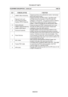
KEY
NOMENCLATURE
FUNCTION
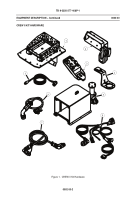
1
CREW II Mount Assembly
Supports primary unit located above exterior fuel storage
tank at left rear of carrier.
2
Remote Control unit
(RCU)/Personal Digital
Assistant (PDA) Assembly
Supports the RCU and PDA cradle.
The PDA cradle
provides hands-free operation of the PDA while the
operator is in the carrier.
It can also be used for charging
the PDA main battery and the PDA internal memory
battery.
Power is provided via the vehicle power cable.
3
Antenna Bracket
Stows and secures CREW II antenna when not in use.
4
CREW II Global Positioning
System (GPS) Mount
Provides the GPS antenna and exterior bracket with
hardware to mount the GPS antenna.
5
Enclosure Assembly
Provides ballistic and environmental protection to the
CREW II primary unit necessary with exterior mounting.
6
Power Harness
Provides power to the carrier cradle from the carrier power
source.
It contains a 5 amp in-line circuit breaker.
The
circuit breaker provides over-current protection to the PDA.
If the circuit breaker trips due to over-current condition, the
circuit breaker can be reset.
7
RCU Cable
Main interface cable between CREW II Primary Unit
located in the rear of the carrier and the RCU.
8
Tactical PDA Cable
Connects the RCU interface cable to the RCU.
This cable
is used when the PDA is being operated in the PDA
(carrier) cradle (2) or desktop cradle.
9
GPS Cable
Provides GPS positioning data from the GPS sensor to the
CREW II Primary Unit.
Back to Top

