TB-9-2350-277-40-P-1 - Page 22 of 100
TB 9-2350-277-40&P-1
EQUIPMENT DESCRIPTION – Continued
0002 00
0002 00-4
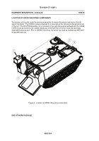
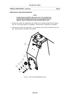
LOCATION OF CREW II MOUNTING COMPONENTS
The primary unit mounts inside the enclosure assembly (5) above the exterior fuel tank on the left
side of the carrier.
The CREW II antenna bracket (3) is mounted on the mid point at the extreme rear
of the hull.
The RCU/PDA assembly (2) is mounted on the right side engine bulkhead with the CREW
II GPS mount and antenna (4) located just above on the right front of the roof over the secondary
SINCGARS antenna port.
Prior to CREW II mounting, the carrier hull must be modified per WP 0003
00 and WP 0004 00.
Figure 2.
Location of CREW II Mounting Components
END OF WORK PACKAGE
Back to Top


