TB-9-2350-277-40-P-1 - Page 26 of 100
TB 9-2350-277-40&P-1
REMOVAL PROCEDURES – Continued
0003 00
0003 00-2
NOTE
Tag leads for identification to aid in installation.
1.
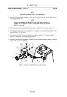
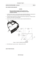
Disconnect left side stoplight-taillight circuit 21 lead (7), circuit 22 lead (8), and circuit 24 lead (9)
from stoplight-taillight (13).
NOTE
If vehicle is equipped with bar armor, removal of upper left fuel tank
support, four screws, flat washers, and two lock washers is required
prior to continuing.
2.
Remove two screws (4), lockwashers (3), and washers (2) from top of mounting bracket (1).
3.
Remove bottom two screws (12), lockwashers (11), washers (10), and mounting bracket (1) with
stoplight-taillight (13) from carrier.
4.
Remove two screws (6) and lockwashers (5) from stoplight-taillight (13).
Separate stoplight-
taillight (13) and gasket (14) from mounting bracket (1).
5.
Retain stoplight-taillight and gasket for installation, return mounting bracket to supply.
Discard all
screws, lockwashers, and washers.
Figure 1.
Stoplight-Taillight Mounting Bracket Removal
Back to Top

