TB-9-2350-277-40-P-1 - Page 35 of 100
TB 9-2350-277-40&P-1
MODIFICATION PROCEDURES – Continued
0004 00
0004 00-5/6 blank
DRILL CREW II RCU/PDA BRACKET
CAUTION
Remove all equipment and gear from the right side engine
compartment to prevent damage when drilling holes in engine
compartment bulkhead.
1.
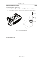
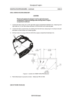
Locate and mark a hole (12) on the right side engine compartment bulkhead (10), measuring from
right side hull (11) 24-7/64 inches and down 4-41/64 inches from inside top plate.
2.
Locate and mark a second hole (12) starting from the first hole, measuring 5 1/2 inches to the left
and down 4-41/64 inches from inside top plate.
3.
Drill two holes (12) using a 3/8 inch drill bit thru engine compartment bulkhead (10).
Figure 4.
Location for CREW II RCU/PDA Bracket
4.
Paint drilled areas to prevent corrosion.
Reference TM 43-0139.
END OF WORK PACKAGE
Back to Top


