TB-9-2350-277-40-P-1 - Page 33 of 100
TB 9-2350-277-40&P-1
MODIFICATION PROCEDURES – Continued
0004 00
0004 00-3
NOTE
The 3-9/16 inch hole in the magnetic drill base plate/template must
align with 3-1/2 inch hole previously marked on hull roof.
Minor
adjustments to position magnetic drill base plate/template may be
necessary.
2.
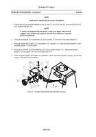
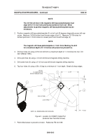
Position magnetic drill base plate/template (3) on hull roof 45 degrees diagonally across left rear
corner.
Measure 1-61/64 inches from the rear edge of hull (1).
Measure 12-7/8 inches for
furthest point and 1-15/32 inches for closest point from the left hull edge (2).
NOTE
The magnetic drill base plate/template is 1 inch thick. Marking the drill
for a maximum depth of 2-1/4 inches will prevent any break thru.
3.
Drill four holes (4) using a 5/16 inch drill bit to a maximum depth of 1-1/4 inches into hull.
DO
NOT BREAK THRU.
4.
Drill a pilot hole (6) using a 1/4 inch drill bit and magnetic drilling machine.
5.
Drill center hole (5) using a 3-1/2 inch saw drill bit and magnetic drilling machine.
6.
Tap four holes (4) using a 3/8 x 16 tap to a minimum of 1 inch depth.
Break all sharp edges.
Figure 2.
Location for CREW II Cable Port
(External Fuel Tank Not Shown)
7.
Paint drilled areas to prevent corrosion.
Reference TM 43-0139.
Back to Top

