TB-9-2350-277-40-P-2 - Page 53 of 100
TB 9-2350-277-40&P-2
INSTALLATION PROCEDURES – Continued
0006 00
0006 00-15
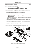
INSTALL GPS ANTENNA CABLES
NOTE
Do not secure cables with tie straps until installation is complete and
the cables have been adjusted at both ends.
1.
Route GPS antenna cables N-type (56) and BNC-type (57) from primary unit location through
clamp (54) up the right side hull to the roof.
2.
Continue routing cables (56) and (57) along existing wiring harness to the rear of the vehicle
through two clamps (55) to GPS antenna riser hull opening.
3.
Measure and pull GPS antenna cable N-type (56) to extend 10 inches beyond bottom of clamp
(54) to primary unit location.
4.
Measure and pull GPS antenna cable BNC-type (57) to extend 24 inches beyond bottom of clamp
(54) to primary unit location.
5.
Secure cables (56) and (57) to existing wiring harness with tie strap (16).
6.
Loop excess cables (56) and (57) at GPS antenna riser hull opening and secure tie strap (16).
Figure 14.
GPS Antenna Cables Installation
Back to Top


