TB-9-3950-253-13-P
PALLETIZED LOAD SYSTEM TRUCK, M1075 and M1075A1 (PLS) AND HEAVY EXPANDED MOBILITY TACTICAL TRUCK, M1120, M1120A2, AND M1120A4 (HEMTT), ENHANCED CONTAINER HANDLING UNIT (E-CHU)
TECHNICAL BULLETIN; OPERATOR AND FIELD MAINTENANCE, INSTALLATION INSTRUCTIONS, AND REPAIR PARTS AND SPECIAL TOOLS LIST
JULY 2009
TB-9-3950-253-13-P - Page 463 of 704
0048.1-5
Change 1
TB 9-3950-253-13&P
0048.1
CONVERT TO SHIPMENT CONFIGURATION – CONTINUED
WARNING
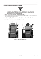
During these procedures, the operator will be required to climb on and around the vehicle.
Be sure to wear suitable footwear and ensure no surfaces are slippery. Wear suitable
gloves and hard hat. Failure to follow this warning may result in injury to personnel.
NOTE
Perform steps 6 through 9 for both right and left sides.
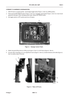
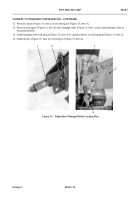
6. Remove clip pin (Figure 5, Item 2) from locking pin (Figure 5, Item 4).
7. Remove locking pin (Figure 5, Item 4) from stowage roller (Figure 5, Item 1) and rotate stowage roller to verti-
cal position.
8. Install locking pin (Figure 5, Item 4) in lower position on locking plate (Figure 5, Item 3).
9. Install clip pin (Figure 5, Item 2) in locking pin (Figure 5, Item 4).
Figure 5.
Reposition Stowage Roller Locking Pins.
048
467-179
1
2
3
4
Back to Top


