TB-9-3950-253-13-P
PALLETIZED LOAD SYSTEM TRUCK, M1075 and M1075A1 (PLS) AND HEAVY EXPANDED MOBILITY TACTICAL TRUCK, M1120, M1120A2, AND M1120A4 (HEMTT), ENHANCED CONTAINER HANDLING UNIT (E-CHU)
TECHNICAL BULLETIN; OPERATOR AND FIELD MAINTENANCE, INSTALLATION INSTRUCTIONS, AND REPAIR PARTS AND SPECIAL TOOLS LIST
JULY 2009
TB-9-3950-253-13-P - Page 95 of 704
0008-17
Change 1
TB 9-3950-253-13&P
0008
RELEASE CONTAINER FOR UNLOADING – CONTINUED
Release and Stow Transport Locks – Continued
0008
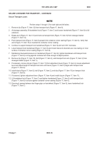
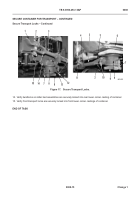
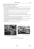
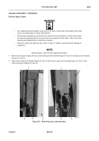
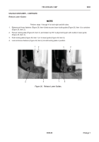
1. At front corner of container, remove clip (Figure 18, Item 10), bolt (Figure 18, Item 2), and transport lock arm
(Figure 18, Item 3) from transport lock (Figure 18, Item 8).
2. If necessary, remove clip pin (Figure 18, Item 11) from adjustment lever (Figure 18, Item 4), loosen adjustment
lever and adjust length of transport lock arm until clevis (Figure 18, Item 5) aligns with stowage bracket
(Figure 18, Item 1).
3. Install clevis (Figure 18, Item 5), bolt (Figure 18, Item 2), and clip (Figure 18, Item 10) on stowage bracket
(Figure 18, Item 1).
4. If loosened, tighten adjustment lever (Figure 18, Item 4) and install clip pin (Figure 18, Item 11).
5. Lift handwheel lock (Figure 18, Item 7) and loosen handwheel (Figure 18, Item 9) to full extension.
6. Rotate anvil (Figure 18, Item 13) and remove transport lock (Figure 18, Item 8) from container corner casting
(Figure 18, Item 6).
7. Push transport lock (Figure 18, Item 8) upward into stowage bracket (Figure 18, Item 14) and rotate anvil
(Figure 18, Item 12) until anvil shoulders are resting on stowage bracket.
8. Maintaining downward pressure on handwheel (Figure 18, Item 9), lift handwheel lock and tighten handwheel
until transport lock (Figure 18, Item 8) is secure against stowage bracket.
9. Ensuring it passes between two finger grips on handwheel (Figure 18, Item 9), lower handwheel lock
(Figure 18, Item 7).
10. Install clip (Figure 18, Item 12) on transport lock (Figure 18, Item 8).
Figure 18.
Release and Stow Transport Locks.
08
10
14
7
8
9
13
11
2
10
9
8
7
6
5
3
4
3
2
1
12
Back to Top

