TM-1-1500-344-23-2 - Page 63 of 240
3-3
NAVAIR 01-1A-509-2
TM 1-1500-344-23-2
15 April 2009
NOTE
On thin sheet material, waviness in the material
may result in false depth readings. Several
readings may be necessary, or it may be
necessary to improvise another method for
determining the depth of the corrosion damage.
The depth gage is not suitable for determining
the depth of a corrosion crack due to the
relatively large size of the indicator pin.
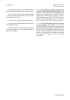
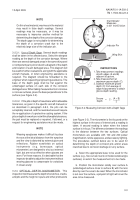
3-2.3.1. Use of Depth Gage. Several depth readings
shall be taken in the affected area. Select the deepest
reading as the depth of the corrosion damage. Where
there are several damaged areas in the same skin panel
or component part, plot or sketch a diagram of the depth
and location of each damaged area. This diagram will
be used for further evaluations, along with the applicable
aircraft manuals, or when engineering assistance is
required. The diagram should be forwarded to the
engineer when requesting engineering assistance. The
base of the depth gage shall be flat against the
undamaged surface on each side of the corrosion
damaged area. When taking measurements on concave
or convex surfaces, place the base perpendicular to the
surface (see Figure 3-2).
3-2.3.2. If the pits or depth of rework are within allowable
tolerances, as given in the specific aircraft manuals or
as described in paragraph 4-8.3, the pits can be
acceptably cleaned, and the reworked area will require
the re-application of a protective coating system. If the
pits or depth of rework are not within allowable tolerances,
the part must be replaced or repaired, if allowed, or a
request for engineering assistance must be made.
NOTE
Wearing eyeglasses makes it difficult to place
the eye at the ideal distance from the eyepiece
and the view is distorted by external glare and
reflections. Rubber eyeshields on optical
instruments (e.g. borescope, optical
micrometer) are designed to shut out external
light, but are not as effective when glasses are
worn. For these reasons, it is desirable that the
inspector be able to adjust the instrument without
wearing glasses to compensate for variations
in visual acuity.
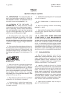
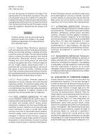
3-2.4. OPTICAL DEPTH MICROMETER. This
inspection tool measures the depth of scratches, cracks,
and pits and the height on spurs and other protrusions
Figure 3-2. Measuring Corrosion with a Depth Gage
0
5
10
15
20
25
20
15
10
5
Dial Indicator
Measures
0.001 Inch/Division
Indicator Pin
Wing Skin
AB
C
1. Take measurement readings
at both edges (A and B)
adjacent to groove.
2. Take measurement at
maximum groove depth (C).
3. Subtract maximum groove
depth (C) from average of
edge measurements to obtain
groove depth reading.
INSTRUCTIONS
±
Groove
Depth
=
(A + B)
2
C -
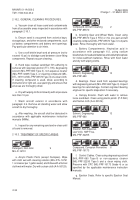
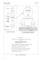
(see Figure 3-3). The micrometer is first focused on the
highest surface in the area of interest and a reading is
taken. A second reading is taken when the lowest
surface is in focus. The difference between the readings
is the distance between the two surfaces. Optical
micrometers are available with 100 and 200 power
magnification, reticle eyepieces, and accessory lighting.
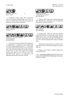
The procedures outlined below are to be used for
determining the depth of corrosion pits and/or areas
reworked due to corrosion damage on any surface.
a. Select the appropriate base to be used for the
surface (e.g., flat, curved, round, or inside/outside angle
surfaces) on which the measurement is to be made.
b. Position the micrometer solidly over surface A
(undamaged surface close to surface B) with the lens
directly over the area to be read. When the micrometer
is set over the surface, a pinpoint of light will cover the
area to be measured.
Back to Top


