TM-1-1500-344-23-2 - Page 70 of 240
3-10
NAVAIR 01-1A-509-2
TM 1-1500-344-23-2
15 April 2009
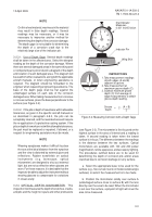
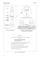
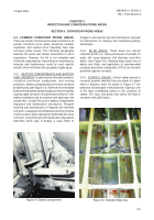
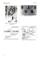
Figure 3-7. Control Cables
3-5.4. ELECTRICAL CONNECTORS. Some electrical
connectors are potted with a sealant compound to
prevent the entrance of water into the areas of connectors
where wires are attached to pins. Rubber O-rings are
also used to seal moisture out of the mating area of pin
connections. Moisture will get into electrical plugs and
cause failure. It is necessary that such plugs be
disconnected periodically for inspection and corrosion
treatment. The use of unauthorized sealants or potting
materials can cause severe damage to affected
connectors or components. Refer to Volume III for
authorized avionic materials and procedures.
3-5.5. ENGINE FRONTAL AREAS AND AIR INLET
DUCTS. Since these areas are constantly abraded by
dirt, dust, and gravel, and eroded by rain, special
attention shall be given to:
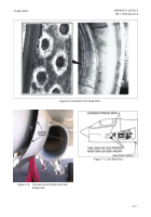
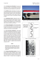
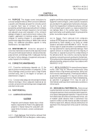
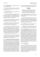
a. Engine frontal areas (see Figure 3-8).
b. Leading edges of engine and air inlet ducts,
including hardware inside ducts (see Figures 3-9 and
3-10).
c. Due to heat dissipation requirements, oil cooler
cores are not usually painted. Engine accessory
mounting bases may have small, unpainted areas on
the machined mounting surfaces. With moist, salt-laden
air flowing over these surfaces, they are vulnerable to
corrosion.
3-5.6. EXHAUST IMPINGEMENT AREAS. Exhaust
impingement areas include areas exposed to engine,
rocket, and missile exhausts, gun blast, or any other
Figure 3-8. Jet Engine Frontal Area
Back to Top


