TM-1-1500-344-23-2 - Page 66 of 240
3-6
NAVAIR 01-1A-509-2
TM 1-1500-344-23-2
15 April 2009
not cover the opening, the material at the edge of the
opening affects the mechanism of penetrant entry and
exit and greatly reduces the reliability of the inspection.
Coatings at the edge of the flaw may also retain penetrant,
causing background fluorescence. An inspection method
other than penetrant must be used if the organic coating
cannot be stripped or removed from the surface to be
inspected.
WARNING
Chemical etching shall only be performed by
personnel trained and certified in the proper
handling and application of the materials due to
their hazardous nature.
3-2.5.3.3. Smeared Metal. Mechanical operations,
such as shot peening, machine honing, abrasive blasting,
buffing, wire brushing, grinding, or sanding, will smear
or peen the surface of metals. This mechanical working
closes or reduces the surface opening of any existing
discontinuities. Mechanical working (smearing or
blending) also occurs during service use when parts
contact or rub against each other. Penetrant inspection
will not reliably indicate discontinuities when it is
performed after a mechanical operation or service use
that smears or peens the surface. Chemical etching
(e.g. Flicks on aluminum alloys and Shantz on Inconels)
prior to penetrant operations is recommended to improve
test sensitivity when smeared metal is present.
3-2.5.3.4. Porous Surfaces. Penetrant inspection is
impractical on porous materials with interconnected
subsurface porosity. The penetrant rapidly enters the
pores and migrates through the network. This results in
an overall fluorescence or color that masks any potential
discontinuity indications. In addition, removal of the
penetrant may not be possible after the inspection.
3-2.6. EDDY CURRENT INSPECTION. The eddy
current inspection method may be used to detect or
evaluate surface and subsurface corrosion. This method
can detect and evaluate uniform surface pitting,
intergranular, exfoliation (corrosion around fasteners),
and stress corrosion. Detection of corrosion with eddy
current techniques is used on aircraft skins where
corrosion may occur on inaccessible interior surfaces.
Corrosion usually occurs in areas where moisture is
entrapped. If relatively uniform thinning is expected,
corrosion detection may be simply a matter of thickness
measurement. In most instances, corrosion is confined
to smaller localized areas of relatively small diameter.
As skin thicknesses increase, sensitivity to small areas
and shallow depths of corrosion is reduced. Corrosion
on either member of a faying surface may be detected.
Eddy current can also be used for corrosion removal
inspections, but is less sensitive than liquid penetrant.
3-2.7. ULTRASONIC INSPECTION. Ultrasonic
inspection provides good resolution to evaluate material
loss and thickness. This method may be used to detect
exfoliation, intergranular, uniform surface, and stress
corrosion. Ultrasonic thickness gaging is included in
this method. Ultrasonic inspection for far side pitting
and internal exfoliation corrosion may be accomplished
using shear ("S") wave and longitudinal ("L") wave
techniques. The use of a delay line transducer is
recommended for "L" wave inspection. The delay will
improve resolution of both near and far surface corrosion.
Technique development is required for specific
applications.
3-2.8. RADIOGRAPHIC INSPECTION. Radiographic
inspection provides the best resolution for detection of
surface and subsurface corrosion flaws when no other
method can accomplish the inspection. The drawback
of radiography is the high equipment cost and the high
man-hour requirements to perform an on-aircraft
radiographic analysis. Radiographic inspection is used
in combination with ultrasonics to determine the condition
of aluminum honeycomb.
3-3. EVALUATION OF CORROSION DAMAGE
.
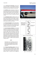
Visually determine if corrosion is in an area which has
previously been reworked. If the corrosion damage is
located in an area that has been previously ground out,
measure the damage to include the material which has
previously been removed. A straight edge and a 10X
magnifying glass may be used to assist in determining
if an area has previously been reworked. Place the
straight edge across the area being examined at various
angles and check for irregularities, low spots, or
depressions (see Figure 3-4). If any irregularities, low
spots, or depressions are found, and a visual
determination cannot verify previous rework, closely
examine the suspected area and the surrounding area
using a 10X magnifier. After determining that the area
has been previously reworked, evaluate the depth of
the previous rework (i.e., grind-out) to determine if
further metal removal will exceed grind-out limits
specified in the applicable aircraft manuals or as specified
in paragraph 4-8.3. Depth measurements can be made
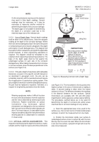
using the depth gage as described in paragraph 3-2.3.
Back to Top


