TM-3-1040-279-12-P - Page 183 of 389
TM 3-1040-279-12&P
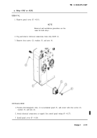
e. PURGE Switch.
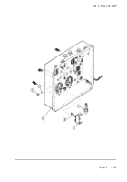
REMOVAL
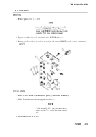
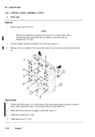
1. Remove panel cover (P. 4-110).
NOTE
Removal and installation procedures are the
same for both PURGE switches. When re-
moving right PURGE switch, disconnect cable
assembly CU-1 from fire detection unit.
2. Tag and unsolder electrical connections from PURGE switch (1).
3. Remove nut (2), washer (3) and key washer (4) and remove PURGE switch (1) from instrument
panel (5).
INSTALLATION
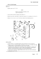
1. Install PURGE switch (1) in instrument panel (5) and secure with nut (2).
2. Solder electrical connections as tagged to switch (1).
NOTE
If cable assembly CU-1 was disconnected, re-
connect cable CU-1 to fire detection control
unit.
3. Install panel cover (P. 4-110).
Change 2
4-115
Back to Top

