TM-3-1040-279-12-P - Page 187 of 389
TM 3-1040-279-12&P
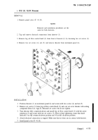
i. FOG OIL FLOW Rheostat.
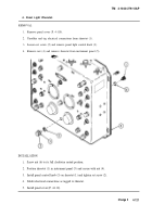
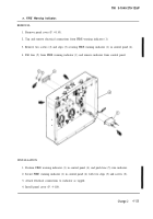
REMOVAL
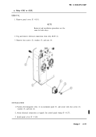
1. Remove panel cover (P. 4-110).
NOTE
Removal and installation procedures are the
same for both rheostats.
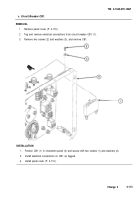
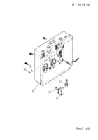
2. Tag and remove electrical connections from rheostat (1).
3. Remove fog oil flow control knob (2) from front of rheostat (1) by loosening two set screws (3).
4. Remove two set screws (4), nut (5) and remove rheostat from instrument panel (6).
Position rheostat (1)
INSTALLATION
1.
2.
3.
in instrument panel (6) and secure with two screws (4) and nut (5).
Remove set screws (3) from fog oil flow control knob (2) and coat set screw threads with sealing
compound (Item 11A, App E). Reinstall set screws but do not tighten.
Turn rheostat fully counterclockwise and install fog oil flow control knob (2) with the arrow
pointing at 0 and secure with two set screws (3). Prior to final tightening, insure that knob
indicates 0 in full counterclockwise position and 10 in full clockwise position.
Attach electrical connections as tagged. Make sure that no wires are in contact with rheostat.
Install panel cover (P. 4-110).
4.
5.
Change 2
4-119
Back to Top

