TM-3-1040-279-12-P - Page 178 of 389
TM 3-1040-279-12&P
4-28 CONTROL PANEL ASSEMBLY
This task covers removal and installation of panel cover and replacement of:
a.
b.
d.
e.
f.
g.
c.
Relay K103 or K203
(P. 4-111)
h.
Toggle Switches (FOG OIL, FUEL,
i.
POWER, FIRE/TEST or ENGINE)
(P. 4-112)
j.
Circuit Breaker CB1
(P. 4-113)
k.
Indicator Lights
(P. 4-114)
l.
PURGE Switch
(P. 4-115)
m.
Cable Assembly
(P. 4-116)
n.
SMOKE TEMP Indicator
(P. 4-117)
o.
Panel Light
(P. 4-118)
FOG OIL FLOW Rheostat
(P. 4-119)
Terminal Board TB11 or TB21
(P. 4-120)
Panel Light Rheostat
(P. 4-121)
Fire Detection Control Unit
(P. 4-122)
Lamps
(P. 4-124)
FIRE Warning Indicator
(P. 4-125)
Cable Assembly CU-1
(P. 4-126)
INITIAL SETUP
Tools
Equipment Condition
General Mechanic’s Automotive Tool Kit
Control panel removed from vehicle (P.
4-20).
SC 5180-90-CL-N26
Materials
Soldering gun (shop equip-common No. 1)
Solder (Item 12A, App E)
Screwdriver A116-3
Tie down straps (Item 13, App E)
Sealing compound (Item 11A, App E)
Insulation sleeving (Item 7C, App E)
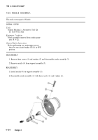
Panel Cover
REMOVAL
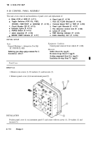
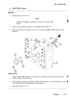
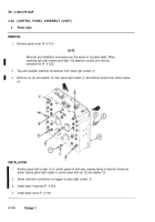
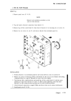
1. Remove ten screws (l), 20 washers (2), and ten nuts (3).
2. Remove panel cover (4) from instrument panel (5).
INSTALLATION
Position panel cover (4) on instrument panel (5) and secure with ten screws (1), 20 washers (2) and
ten nuts (3).
4-110
Change 3
Back to Top

