TM-3-1040-279-12-P - Page 240 of 389
TM 3-1040-279-12&P
4-42 FOG OIL TANK ASSEMBLY.
This task covers replacement of:
a.
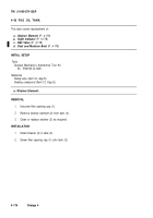
Fog Oil Tank and Insulating Pads
(P. 4-172)
b.
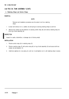
Retaining Straps and Anchor Straps
(P. 4-174)
INITIAL SETUP
Tools
Materials
General Mechanic’s Automotive Tool Kit
Dry Cleaning Solvent (item 4, App E)
SC 5180-90-CL-N26
Rags (item 11, App E)
Adhesive (Item 1, App E)
a.
Fog Oil Tank and Insulating Pads.
NOTE
The following procedure applies to one insulating pad. All pads are
removed/installed the same way.
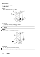
REMOVAL
1.
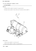
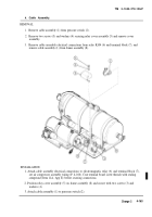
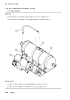
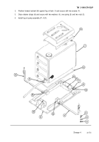
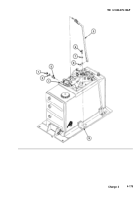
Remove fog oil pump assembly (P. 4-21).
2.
Use appropriate container and drain fog oil tank (1) thru ball valve (2).
3.
Loosen and remove nut (3), washer (4) and spring (5) on both retainer straps (6).
4.
Loosen but do not remove two screws (7) securing forward restraint (8), and move restraint away
from fog oil tank (1).
5.
Remove fog oil tank (1) from baseplate (9)
INSPECTION/REPAIR
1.
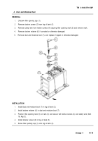
Inspect baseplate pad (10), forward restraint pad (11), side restraint pads (12), top restraint pad (13)
and rear restraint pad (14).
2.
Replace pads if tom or otherwise damaged (Fig. 11 thru 14, App G).
3.
Lift edge of pad (11) with sharp tool.
4.
Remove pad completely from restraint (8).
5.
Clean restraint mounting surface with dry cleaning solvent (Item 4, App E) and rags (Item 11, App
E).
6.
Apply thin coat of adhesive (Item 1, App E) to pad (11) and restraint (8). Allow to dry for 10 to 20
minutes, then press surfaces together.
INSTALLATION
NOTE
For installation it may be necessary to remove one of the side restraints (P.
4-174).
1.
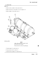
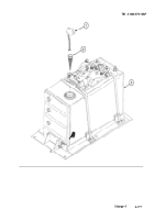
Position fog oil tank (1) in baseplate (9).
4-172
Change 4
Back to Top

