TM-5-2350-262-20-1 - Page 560 of 776
TM 5-2350-262-20-1
Change 4
4-210.5 (4-210.6 Blank) (4-211 through 4-212 deleted)
I
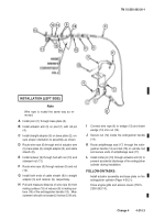
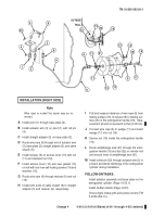
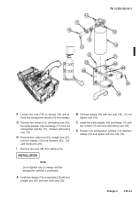
Pull and measure distance of wire rope (6) from
mating surface (19) of reducer (9) to mating sur-
face (20) of fire extiniguisher handle (18).
Mea-
surement should not exceed 2 inches (5.08 cm).
J
Connect wire rope (6) to wedge (17) and insert
wedge (17) into nut (16).
K
Secure nut (16) inside fire extinguisher handle
(18).
L
Route antipilferage seal (21) through fire extin-
guisher handle (18) and tab (22) on vehicle hull
and secure ends of antipilferage seal (21).
M
Install cotter pin (23) through actuator arm (3) to
prevent accidental discharge of fire extinguisher
cylinder during installation.
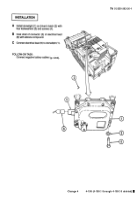
A
Install pivot (1) through base plate (2).
B
Install actuator arm (3) on pivot (1) with roll pin
(4).
C
Install straight adapter (5) on base plate (2).
D
Route wire rope (6) through end of actuator arm
(3), base plate (2), straight adapter (5), and cable
sheath (8).
E
Install reducer (9) on access cover (10) with nut
(11) and stamped nut (12).
F
Install access cover (10) and new gasket (13)
on hull with four new self-locking screws (14) and
washers (15).
G
Route wire rope (6) through reducer (9) and nut
(16).
H
Install both ends of cable sheath (8) to straight
adapter (5) and reducer (9), respectively.
Note
Wire rope is routed the same way as re-
moved.
FOLLOW-ON TASKS:
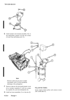
Install actuator assembly and base plate on fire
extinguisher cylinder (Page 4-212.1).
Install muffler shields (Page 4-607).
Close engine intake grills and access covers (TM
5-2350-262-10).
11
21
23
3
6
8
5
1
4
6
18
19
20
8
12
9
17
16
18
2
22
INSTALLATION (RIGHT SIDE)
OUTSIDE
HULL
6
14
15
13
10
Back to Top

