TM-5-2350-377-14-P - Page 36 of 335
TM 5-2350-377-14&P
OPERATING PROCEDURES - continued
NOTE
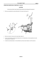
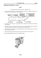
Record measurement from middle of top of No. 4 roadwheel to track.
5. Dismount vehicle and inspect track. The track should just touch the top of No. 3 roadwheel, and should be 1-1/4
to 2 inches (3.2 to 5.1 cm) above the top of No. 4 roadwheel.
6. If the track is more than 2 inches (5.1 cm) above the top of No. 4 roadwheel, loosen the track by moving the track
loosening switch.
7. If the track is less than 1-1/4 inches (3.2 cm) from the top of No. 4 roadwheel, tighten the track as necessary by
moving that side track tensioning switch. This operation will tighten that side track only.
8. Repeat steps 5 through 7 for track on the other side. Repeat operation until both tracks have a gap 1-1/4 to 2 inches
above the top of No. 4 roadwheel.
9. Move vehicle slightly forward to remove any slack in left and right tracks from behind the sprocket.
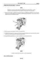
10. Place SPRUNG/UNSPRUNG control lever (1) in UNSPRUNG mode.
0005 00-7
0005 00
1-1/4 TO 2 IN. (3.2 TO 5.1 CM)
BETWEEN TOP OF
ROADWHEEL AND
BOTTOM OF TRACK
GROUND LEVEL
NO. 3 ROADWHEEL
NO. 4 ROADWHEEL
TRACK SHOULD
TOUCH HERE
MEASURE FROM
MIDDLE OF TOP
OF ROADWHEEL
FRONT OF
VEHICLE
1
Back to Top

