TM-5-3805-254-14-P-2 - Page 216 of 894
TRUCK SERVICE MANUAL
BRAKES-AIR
c.
Assemble gasket and guide screw into plunger
housing.
4.
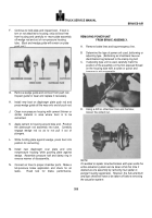
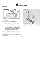
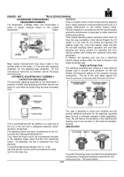
AUTOMATIC ADJUSTING PLUNGERS
a.
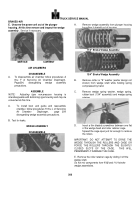
Grease coat the inside and outside surfaces of
both the adjusting plunger and the adjusting
sleeve.
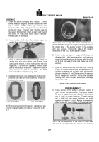
Place the plunger into the plunger
housing aligning plunger key-way slot with the
guide hole and assemble adjusting pawl* Push
pawl back flush with inside of plunger and hold in
this position with a small screwdriver while
installing grease coated adjusting sleeve.
NOTE
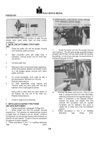
The adjusting pawl has teeth and flats on one
end and a chamfered edge on the other end.
Coat pawl
with grease and insert it into the guide hole,
teeth first,
and IMPORTANT
with chamfer toward the brake shoe.
This aligns the pawl and sleeve teeth and the flats with
the key-way slot.
Back to Top

