TM-5-3805-254-14-P-2 - Page 335 of 894
TRUCK SERVICE MANUAL
ENGINE
The following service tools or tools of equal quality are
considered necessary to repair and or rebuild the cylinder
block as outlined in this section.
Service Tools (Or Equivalent) Required
Service
Tool
Tool Number
Name
ST-526
Boring Machine
ST-1010
Counterboring Tool (Water Hole)
ST-1059
Counterboring Tool (Cylinder Liner)
ST-1064
Adapter Plate
ST-1065
Tool Holder
ST-1081
Boring Tool
ST-1084
Bore Adapter
ST-1096
Lower Bore Chamfer Kit
ST-1168
Counterbore Salvage Tool
ST-1177
Boring Tool (Main Bearing Bore)
ST-1228
Camshaft Bushing Drive Kit
ST-1250
Cylinder Liner Bore Salvage Tool
ST-1252
Concentricity Gauge
ST-1272
Head Capscrew Thread Salvage
Tool
Desirable (Or Equivalent) Service Tools
ST-205
Plug Gauge (Connecting Rod)
ST-547
Gauge Block
ST-560
Ring Groove Gauge
ST-561
Checking Fixture (Connecting Rod)
ST-563
Locating Mandrel (Connecting Rod)
ST-598
Bushing Mandrel (Gear Cover)
ST-861
Chamfering Tool (Connecting Rod)
ST-896
Ring Gauge (Connecting Rod)
ST-897
Ring-Gauge (Connecting Rod)
ST-903
Ring Gauge (Main Bearing Bore) ST-
1171
Bushing Mandrel (Accessory Drive) ST-
1178
Puller (Main Bearing Cap)
ST-1184
Cylinder Liner Hold Down Tool
ST-1242
Mandrel Set
Standard Tools-Obtain Locally
Dial Bore Indicators
1/2 inch Electric Drill
Micrometers
CYLINDER BLOCK
INSPECTION
Before any parts are discarded or used again a careful
inspection must be performed.
The inspection should include
wearing surfaces and general over-all conditions.
Note
: Inspection of cylinder block must be performed on a flat
surface to prevent distortion, do not leave on engine stand.
Using Dye Penetrants To Locate Flaws
Use dye penetrate method for locating cracks, porosity, leaks,
etc.
Clean suspected defective area with kerosene or other
grease-removing cleaner.
Apply dye penetrate allowing time for it to dissolve or enter into
the defect (usually about fifteen minutes); do not "force" dry.
Remove all excess penetrant and apply developer so defect
will stand out; cracks usually show up as a solid or dotted line;
however, caution must be observed as this can be a non-
damaging forging lap.
Porosity usually shows up as dots in
local areas.
The wider the area spreads, the larger the defect.
Corrosion
Corrosion most frequently occurs on portions of block nearest
cylinder liners and is evidenced by pitting.
Discard block if
area cannot be cleaned, or if area is distorted and cannot be
repaired by sleeving as outlined under "Parts Replacement
and Repair" following.
Camshaft Bushings
Use inside micrometers or dial bore gauge to measure
camshaft bushing inside diameter.
Mark bushings for
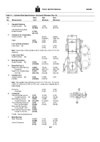
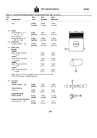
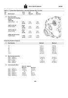
replacement if worn larger than "Worn Limit" (Table 1-1) (1) or
are chipped, scored or scratched.
If bushings have turned in
block bore, check block bore size; see Table 1-1 (1).
Make
certain oil passages between bushings and block oil holes are
properly aligned.
If bushing replacement is necessary, see
"Parts Replacement and Repair."
Cylinder Liner Counterbore
1.
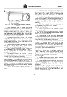
Check upper liner counterbore and remove burrs, dirt, etc.,
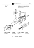
so liner will enter without distortion (A, Fig.
1-1).
If
counterbore exceeds limits listed in Table 1-1 (2) for the top
0.250 inch [6.35 mm] depth, mark blocks for counterbore
repair.
The counterbore ledge must be smooth and
perpendicular to the liner bore to within 0.005 inch [0.13mm]
total indicator reading.
Use a straight edge to check flatness
of top of block.
Refer to "Top Surface Refinishing."
331
Back to Top

