TM-5-3805-254-14-P-2 - Page 336 of 894
TRUCK SERVICE MANUAL
ENGINE
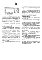
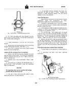
A.
Upper Liner Counterbore
B.
Counterbore Depth
Fig.
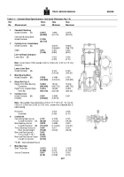
1-1 (N 10103).
Cylinder liner counterbore dimension
location.
2.
Check counterbore depth so installed liner will be
assembled to correct protrusion and to determine if refinish of
counterbore surface is necessary.
Depth of counterbore on a
new block is listed in Table 1-1 (2).
If worn to or beyond limit,
the cylinder block must be salvaged using ST-1250 Cylinder
Liner Bore Salvage Tool or replaced.
If worn less than worn
limit, the surface can be refinished and shims installed under
the cylinder liner to restore proper protrusion.
3.
Installed cylinder liners must protrude 0.003 to 0.006
inch [0.08 to 0.15 mm] above block.
To check for proper
protrusion without installing a liner: a.
Measure liner flange
outside bead with micrometer.
Do not include bead on top of
liner flange in taking measurement.
b.
Measure block counterbore depth with dial indicator
depth gauge or ST-547 Gauge Block.
Always measure
counterbore depth on ledge at the edge of liner bore.
c.
Check depth at four equidistant locations.
Ledge must
not be "cupped" more than 0.0014 inch [0.036 mm].
Depth
must not vary more than 0. inch [0.03 mm] throughout
counterbore circumference.
d.
Counterbore must always be resurfaced if it slants
downward toward the center or if dimensions do not meet
standards.
See "Parts Replacement and Repair."
e.
Subtract counterbore depth from liner flange thickness
to determine amount of shims and depth of counterbore cut
that must be used to provide 0.003 to 0.006 inch [0.08 to 0.15
mm].
liner protrusion; 0.007 inch [0.18 mm] shims are thinnest
available.
If material to be removed will result in a counterbore
depth exceeding worn limit, block cannot be reused, unless a
sleeve can be installed.
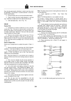
4.
The most accurate method of checking protrusion is as
follows:
a.
Install liner in block with proper number of liner shims
beneath the flange.
Shims are available from 0.007 to 0.068
inch [0.18 to 1.73 mm].
Use ST-1005 or ST-1184 cylinder liner
hold-down tool.
Tool should be spaced so even load will be
applied.
b.
Use ST-547 Gauge Block and check liner protrusion
above the cylinder block at four equidistant points outside the
bead.
Add or remove shims from beneath the liner flange as
needed to reach 0.003 to 0.006 inch [0.08 to 0.15 mm]
protrusion.
c.
With liner installed, check for out-of-round as
described under "Install Liner in Block," Group 14.
Cylinder Liner Lower Bore
1.
Install a new cylinder liner in the block without packing
rings or crevice seal.,
2.
Desirable clearance between liner and block should be
as listed, but liner contact with block is permissible as long as
it does not cause liner out-of-round.
3.
If clearances do not fall within limits, recheck after
counterboring, limits do not apply with cylinder head installed
and tightened to operating torque.
If clearance is not correct,
check lower block packing ring bore inside diameter.
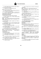
4.
Lower liner bore concentricity should be checked with
ST-1252.
If a piston seizure has occurred or after
counterboring the cylinder block, check the counterbore to
lower cylinder liner bore concentricity.
Follow Service Tool
Instructions, Page 344.
Liner bore should be concentric within
0.005 inch [0.13 mm] total indicator reading.
Main Bearing Caps
Caps must fit in block with no perceptible clearance or
"shake." Milled faces of cap must always rest on mating
portion of block to prevent distortion during tightening.
Replacement caps are available as service parts.
Main Bearing Bore
1.
Assemble main bearing caps to block in operating
position.
Tighten capscrews to operating tension.
2.
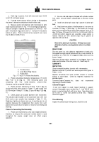
Gauge main bearing bores horizontally, vertically and
diagonally with dial bore gauge or inside micrometers properly
adjusted to ST-903 Ring Gauge.
See Table 1-1 (3) for
dimensions.
ST-1177 Boring Tool may also be used to check main bearing
bore alignment, see Service Tool Instructions, Page 347 If it is
definitely determined that a main bearing cap has been
distorted, mark block for reaming.
332
Back to Top

