TM-5-3805-254-14-P-2 - Page 344 of 894
TRUCK SERVICE MANUAL
ENGINE
4.
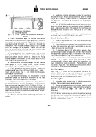
Insert mandrel with all components listed in Step "2"
into connecting rod bushing bore.
5.
Align Detail (4) with middle of boss on rod.
Note
:
Be sure to line up oil holes.
6.
Using an arbor press,. press bushing into bore until
Detail (4) contacts side of rod pin boss.
7.
To install thick-walled bushings in rods which have
been resized at crankpin end, install in same manner as
outlined in Steps 2 through 6 above.
Bore Rod Piston Pin Bushing
1.Fill lubricating holes with soap to keep out shavings.
2.
Mount connecting rod in ST-526 Tobin-Arp Boring
Machine or equivalent.
Note
:
Lower mandrel should have only the two horizontal
blades in place to properly locate the side position of the
piston pin end of rod.
3.
See instruction booklet furnished with ST-526 for
operating procedure.
4.
Bore bushing to 2.001 to 2.0015 inch [50.83 to 50.84
mm] inside diameter.
Remove rod from ST-526 and check
size with ST-205 Plug Gauge.
5.
Remove sharp edges with a scraper.
6.
Remove shavings and soap, wash in mineral spirits
and dry with compressed air.
7.
Check all dimensions on rebushed and rebored rods
on ST-561 Checking Fixture as previously described.
Note
:
All connecting rods used in an engine should have the
same
part number
and
letter code.
Never attempt to
interchange caps.
Chamber Piston Pin Bore
1.
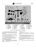
ST-861 Chamfering Tool is used to chamfer tapered
piston pin bushing bore, if not chamfered.
2.
Install proper bushing tool detail by use of flat-head
screw.
3.
Set the guide screw holder.
in position; there are three
notches, so guide screw wi ll follow on face of bore.
4.
Adjust tool bit until point just clears guide screw and
tighten in position with two set screws.
5.
Install unit into bore.
6.
Adjust the guide screw (up or down) until tool bit just
engages bore.
Note
:
A slight pressure is required against guide screw.
To obtain this pressure, tighten set screw in end of holder
against guide screw.
7.
Insert drive ratchet and turn tool one complete turn to
clean up edge of bore.
8.
Loosen guide screw and again turn tool one or more
complete turns to give a clean cut.
Note
:
Repeat until a uniform chamfer of 0. to
0.060
inch
[1.02 to 1.52 mm] depth is reached.
9.
Remove tool from bore, turn rod over and chamfer
other side of bore.
10.
With both sides chamfered, remove tool.
11.
Use emery cloth to remove any sharp edges which
may have been left on chamfer.
12.
Wash rod before bushing installation.
PISTONS AND PISTON RINGS
Piston Rings
New rings should be checked in cylinder liner in which they are
to be used to make sure the gaps are correct.
1.
Insert each ring in mating cylinder liner; position with
head of piston so it is seated squarely in ring travel area of
liner.
2.
Measure ring gap with a feeler gauge.
Gap should fall
within limits given in Table 1-1 (14).
3.
Never file or stone chrome-plated rings and never use
chrome-plated rings in chrome-plated cylinder liners.
4.
Check current parts catalogs to assure use of proper
ring/piston
combination.
When
used,
chrome-plated
compression ring is always installed in top piston ring groove.
Pistons
INSPECTION
1.
Check top and second ring grooves with ST-560 Ring
Groove Gauge.
Shoulders of gauge must not touch ring
groove lands if piston is to be reused.
If shoulders touch,
discard piston.
2.
If ST-560 is not available, check wear with a segment
of a new ring and a feeler gauge.
340
Back to Top

