TM-5-3805-254-14-P-2 - Page 346 of 894
TRUCK SERVICE MANUAL
ENGINE
wear; discard if damaged or worn smaller than 0.
inch
[2.11 mm].
New dimensions are 0.093 to 0.098 inch [2.36 to
2.49 mm].
Gear
1.
Remove gear if chipped, cracked or visibly worn.
Gear
is press-fit on camshaft.
2.
Place camshaft in a press between V-blocks.
Heat
gear with heating torch to 300 deg. to 400 deg. F [148 to 204
deg. C].
CAUTION
Never support gear on outer gear surface. Always
support hub area with V-blocks or equivalent spacers.
3.
Press camshaft from gear; remove key.
4.
Remove pipe plug from drive end of camshaft; clean
oil passages as required.
Note
:
On engines not equipped with outboard bearing,
camshaft contains an orifice plug 68193.
Do not mix with
other 1/8 inch orifice plugs.
5.
Install pipe plug in drive end of camshaft, if removed.
Torque pipe plug to 5 to 10 ft-lbs [0.7 to 1.4 kg m].
6.
Heat camshaft gear evenly to 400 deg.
F [204 deg.
C]
with heating torch.
Maximum clearance between camshaft
flange and gear face is 0.0015 inch [0.038 mm]; check with
feeler gauge.
7.
Place camshaft in press; insert new key in camshaft.
Press on camshaft gear while hot.
Note
:
Always check timing when a new camshaft or gear is
installed in an engine.
GEAR COVER
INSPECTION
1.
Remove and discard all oil seals.
2.
Check trunnion and/or bushing for wear; replaceable
bushing is available to "rebuild" outside diameter of trunnion
which was not originally equipped with bushing.
3.
Check thrust plates for deep scores or wear beyond
point where removal of gaskets will now allow establishment of
correct camshaft end play.
See Camshaft Installation, Group
14.
PARTS REPLACEMENT AND REPAIR
Gear Cover Trunnion
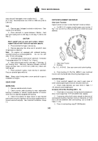
If gear trunnion on cover is to be "bushed," install as follows:
a.
On 855 C.I.D. engines machine gear case trunnion (1
Fig. 1-12) to 4.747 to 4.750 inch [120.57 to 120.65 mm] outer
diameter.
1.
Gear Case Trunion
2.
Bushing
Fig. 1-12.
(N10145).
Gear case cover and trunion bushing.
b.
Press bushing (2) (Part No. 68226-1) over machined
trunnion with chamfered side of bushing toward gear case.
Camshaft Support
1.
Front camshaft supports are used in gear cover of
some turbocharged engines and are one piece aluminum.
2.
Check inside diameter, per wear limits in Table 1-1
(15), discard unserviceable parts.
Accessory Drive Bore Bushing (855 C.
.D.)
1.
Check bore of accessory (fuel pump and compressor)
drive; if worn larger than 1.571 inch [39.90 mm], replace.
2.
If accessory drive shaft is worn enough to allow use of
oversize bore bushing (maintain minimum clearance of 0.003
inch [0.08 mm] between shaft and bushing), use as listed in
Table 1-1 (16).
3.
Press in new bushing using ST-598 Mandrel.
342
Back to Top

