TM-5-3805-254-14-P-2 - Page 347 of 894
TRUCK SERVICE MANUAL
ENGINE
INSTRUCTIONS FOR USE OF SERVICE TOOLS
ST-1010 Water Hole Counterboring Tool
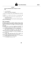
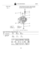
See Service Tool Instructions, Cylinder Heads, Group 2.
ST-1059 Cylinder Liner Counterboring Tool
ST-1064 and ST-1065 Service Tools are used in this
operation.
Assemble tools as follows:
1.
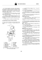
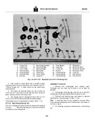
Install ST-1059 driver (1), Fig.
1-13, onto ST-1064
adapter (2) with capscrews (4).
2.
Install ST-1065 Tool Holder (3) onto driver unit (1).
Fasten holder onto drive unit with capscrew (5).
1.
Drive of ST-1059
6.
Handle
2.
Adapter of ST-1064
7.
Plunger
3.
Tool Holder of ST-1065
8.
Locking Screw
4.
Capscrew of ST-1064
9.
Adjusting Nut
5.
Capscrew
10.
Capscrew
and
Washer
Fig. 1-13, (V40156).
ST-1059 Counterbore Tool
PRESETTING TOOL BIT
1.
Loosen thumb screw and push adjusting pin back into
housing.
Tighten thumb screw.
2.
Place tool bit setting gauge onto tool holder with dowel
pins, engaging smaller diameter of tool holder and holding
locating surfaces of housing against flat surface of tool holder.
3.
While holding tool bit setting gauge in the above
position, loosen thumb screw allowing adjusting pin to engage
larger diameter of tool holder.
Tighten thumb screw.
4.
Install tool bit into tool holder.
Set point of tool bit
below larger diameter of tool holder and tighten one setscrew.
5.
Place tool bit setting gauge with dowel pins engaging
smaller diameter of tool holder, holding locating surfaces of
housing against flat surface of tool holder.
6.
Position adjusting pin over point of tool bit.
Loosen
setscrews allowing tool bit point to rest against locating point
of adjusting pin.
Tighten setscrews.
INSTALLATION AND OPERATION
1.
Pull out on handle (6) until plunger (7) will hold tool
holder (3) in the up position.
Place unit on cylinder block with
hold-down holes matching in cylinder block.
2.
Hold onto handle (6) and pull out on plunger (7).
Slowly lower tool holder into counterbore.
Engaging larger
diameter of holder allow tool bit to rest on counterbore ledge.
3.
Loosen locking screw (8) and rotate adjusting nut (9)
in clockwise direction until tool bit clears counterbore ledge.
Tighten locking screw.
4.
Assemble hold-down capscrews and washers (10)
through adapter plate into cylinder block finger tight, then
torque to 50 to 75 ft-lbs (6.9 to 10.4 kg m].
Note
:
Tool holder must rotate freely.
5.
To measure depth of counterbore:
a.
Install depth gauge into gauging hole of adapter plate.
Loosen capscrew and push down on dial indicator to end of
travel.
b.
Pull dial indicator 0.010 to 0.020 inch [0.25 to 0.51
mm] off bottom.
(End of travel.) Tighten capscrew.
c.
Set dial indicator to zero.
d.
Rotate tool holder until red indicator line matches red
line on adapter plate.
e.
Place depth gauge on four counterbore measuring
holes.
The average of the four readings will be the present
depth of counterbore.
See Table 1-1 (2) for counterbore
depth.
6.
To operate counterboring tool:
a.
Loosen locking screw.
Rotate adjusting nut in
counterclockwise direction until tool bit is resting on lowest part
of counterbore ledge and there is clearance between housing
and adjusting-nut.
Note
:
The distance between housing and adjusting nut equals
amount of material that will be removed from counterbore
ledge.
343
Back to Top

