TM-5-3805-254-14-P-2 - Page 339 of 894
TRUCK SERVICE MANUAL
ENGINE
1.
Check for cracks in cylinder liners just under top
flange, at bottom of liner, or above top seal ring groove as
follows:
a.
Magnetic Method.
b.
Dye Penetrants.
2.
Discard any liner with excessive corrosion or erosion
and pits 1/16 inch [1.59 mm] deep or more or if dents, pitting
or fretting on underside of liner flange cannot be removed by
lapping.
3.
Check worn liners with dial bore gauge.
Replace if
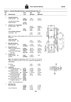
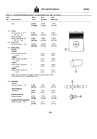
worn more than Worn Limit as shown in Table 1-1 (5).
4.
Deglaze cylinder liner walls.
CLEANING
1.
After liners are deglazed, they must be cleaned
thoroughly with solvent, steam cleaner or hot soap and water.
It is recommended that cleaning operation be ended by
scrubbing bore with a bristle brush to remove as much debris
as possible.
Blow liners dry with compressed air.
Coat bore
of liners generously with clean lubricating oil.
If possible, let
liners stand 5 or 10 minutes.
Use white paper towels to wipe
lubricating oil from liner bores.
Note gray and even black
residue that appears with oil on white towels.
Repeat
application of lubricating oil and wipe off with white paper
towels.
2.
All new cylinder liners should be "prebrushed" and
cleaned before assembly to assure no abrasives are present
in the Lubrite coating.
CRANKSHAFT
Crankshafts are steel forgings with accurately machined and
hardened main and connecting rod journals. Each
shaft
is
balanced for proper weight distribution to insure even forces
during rotation.
DISASSEMBLY AND INSPECTION
1.
If crankshaft gear is chipped, cracked, broken or worn;
remove lockplate and nut (if used).
Note
:
If crankshaft gear condition is satisfactory, do not
remove gear.
2.
Attach a circular-type puller behind the crankshaft
gear.
3.
Apply 75 to 100 ft-lbs [10.4 to 13.8 kg ml on puller
screw.
4.
Heat gear with heating torch not a cutting torch to 300
deg.
to 400 °F [150°
to 205 °C] .,The gear will expand,
making it easier to pull.
Remove gear key.
5.
Inspect crankshaft visually for scratches, nicks, cracks
and obvious wear pattern and measure crankshaft journals
with micrometers.
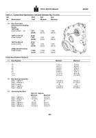
See Table 1-1 (6).
6.
Check
crankshaft
for
out-of-round
condition.
Crankshafts should be reground if main bearing or crankpin
journals are worn out-of-round more than 0.002 inch [0.05 mm]
.
CLEAN DRILLINGS IN CRANKSHAFT
1.
Remove all pipe plugs, clean all drilled oil passages in
crankshaft with a rod and rag as if cleaning a rifle barrel.
2.
Lubricate threads with clean SAE 20W or 30W
lubricating oil, install and tighten plugs to 60 to 96 inch-lb [0.7
to 1.1 kg ml torque.
INSPECT CRANKSHAFT JOURNALS AND THRUST FLANGE
1.
Carefully examine crankshaft journals and thrust
flange at No. 7 main bearing.
If surfaces are scored or
scratched, crankshaft should be reground and undersize rod
and main bearings or oversize thrust rings installed.
2.
Reground crankshafts or those used with undersize
rod · ,and main bearings and/or oversized thrust rings should
be marked so correct bearing shells and thrust rings can be
installed in proper position.
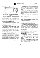
Fig's.
1-3 and 1-4.
3.
The marking for undersize rod and main bearings
should be on front counterweight, oversize thrust ring size on
rear counterweight.
Both thrust ring size and ring location
must be included in stamping as shown in Fig.
1-4.
For example: Front 0.
inch [0.25 mm] and rear 0.020 inch
[0.51 mm].
ASSEMBLY
Install crankshaft gear, if removed.
Note
:
Check parts catalog for correct gear part number.
a.
Install key or dowel pin in shaft.
b.
Heat gear in a pre-heated oven at 450 deg. F [214
deg. C] for a minimum of one hour.
335
Back to Top

