TM-5-3805-254-14-P-2 - Page 348 of 894
TRUCK SERVICE MANUAL
ENGINE
b.
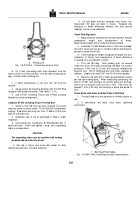
To set the depth of cut, place a feeler gauge of
required thickness between adjusting nut and top of housing.
For example: if 0.005 inch [0.13 mm] of material is to be
removed from counterbore ledge, use 0.005 inch [0.13 mm]
feeler gauge.
Make sure there is no grease or dirt between
adjusting nut and top of housing.
c.
Rotate adjusting nut until feeler gauge is just held
between adjusting nut and top of housing.
Tighten locking
screw.
Remove feeler gauge.
d.
Hold down on handle applying more pressure on tool
bit side and rotate handle in a clockwise direction until unit
turns freely and is bottomed out between adjusting nut and top
of housing.
e.
Measure depth of counterbore as described in Step 5.
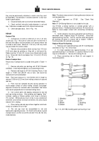
ST-1081 Boring Tool (Lower Cylinder Liner Bore)
ST-1064, ST-1081, ST-1081-52 and ST-1084 Service Tools
are also used in this operation.
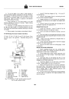
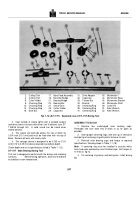
Assemble boring tool as
follows:
1. Drill Motor
8.
Bore Adapter
2. Drive Gear
9.
Tool Holder
3. Torque Reaction Bar
10.
Capscrew
4. Adapter Plate
11.
Capscrew
5. Retaining Nut
12.
Drive Adapter
6. Retaining Nut Handle
13.
Upper Bearing
7. Boring Tool
Fig. 1-14, (V40153), ST-1081 Tool Bit installed in blockST-
1081 Tool Bit installed in block
1.
Install ST-1084 Bore Adapter (8, Fig.
1-14) onto ST-
1081 Boring Tool.
2.
Install ST-1064 Adapter Plate (4) onto boring tool with
3/4 inch recess toward bore adapter.
3.
Engage retaining nut (5) onto boring tool and tighten
retaining nut until boring tool, bore adapter and adapter plate
are secure.
4.
Install ST-1081-52 Tool Holder (9) into boring tool (7)
and tighten in position with capscrews (10).
PRESETTING TOOL BIT
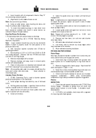
1.
Loosen two setscrews.
Install ST-1081-55 Tool Bit
into tool holder, being sure that spring is in place.
2.
Push in on tool bit until it bottoms on spring.
Lock one
setscrew.
3.
Place tool holder into setting gauge and fasten in place
with capscrew finger tight and position point of tool bit so it will
engage setting nib.
Note
:
Proper nib will be indicated by stamped letters or
numerals for particular engine.
4.
Loosen setscrews allowing point of tool bit to engage
setting nib, then tighten against bit.
5.
Remove tool holder and bit from setting gauge.
Install
in boring tool.
INSTALLATION AND OPERATION
1.
Install assembled boring tool into cylinder block,
allowing bore adapter (8) to engage counterbore and holes in
adapter plate to match holes in cylinder block.
2.
Fasten adapter plate in place, tighten capscrews to 50
to 75 ft-lbs [6.9 to 10.4 kg m] torque.
Install torque reaction
bar (3) into plate.
3.
Install gear drive (2) onto boring tool with 1/2 inch
square drive engaging boring tool and gear drive anchor arm
engaged over the torque reaction bar.
4.
Install drive adapter (12) into drill motor (1)and fasten
in place.
Engage adapter and motor onto gear drive.
5.
Being sure boring tool shaft is in maximum up position,
turn on drill motor.
Initial contact of tool bit with bore will be
intermittent and care should be exercised at start of cut.
While
unit is rotating, apply a slight downward pressure until
maximum depth bf bore is complete.
6.
Pull-up on drive shaft of boring tool (turning clockwise)
until drive shaft is in up position, then repeat procedure to be
sure of a true hole.
344
Back to Top

