TM-5-3805-254-14-P-2 - Page 363 of 894
TRUCK SERVICE MANUAL
8. Use ST-884 Injector Sleeve Cutter in a drill press
with pilot, using a solid stream of good cutting oil to allow
cutter to cut freely without grabbing, etc.
9. Water test cylinder head.
See Page 2-4.
Grind Valves
1. Check valve grinder setting by using a new valve
and an indicator gauge:
a. Check valve in valve grinder on guide area of
stem.
Relieved portions on both ends of guide area are
not necessarily concentric to guide area of stem.
b. Indicate on ground face of valve.
c. Turn valve and mark high spot on head of valve.
d. Rechuck valve 180 deg.
from first position.
e. Repeat (b) and (c).
If high spots are same for
both (a) and (d) position, valve is warped.
If high spots
occur in different positions, chuck is out of alignment.
Runout should not exceed 0.001 inch [0.03 mm].
2. Wet-grind valves to an exact 30 dep.
angle from
horizontal.
Check rim thickness as shown in Fig.
2-7.
If
rim is less than 0.105 inch [2.67 mm], valve is not
suitable for reuse.
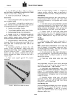
3. Pencil mark valve face as shown in Fig.
2-12,
position in valve guide against a newly ground valve
seat, rotate valve 10 deg.
A good seat will be indicated if
all pencil marks are broken.
If pencil marks are not
broken, tools need dressing or machine has not been
properly adjusted; final check should be made with a
vacuum tester.
4. Valve seats properly ground with precision
equipment
Back to Top

