TM-5-3805-254-14-P-2 - Page 358 of 894
TRUCK SERVICE MANUAL
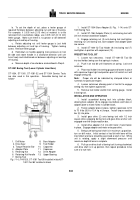
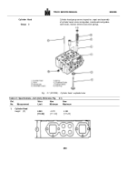
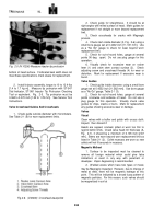
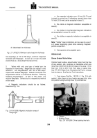
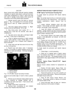
Fig.
2-3 (V10244) Cylinder head installed In ST-1012
Hydrostatic Tester
may not show water leakage.
Discard head if cracked;
replace leaking sleeves.
2, Open water outlet of test fixture; check for free water
circulation through cylinder head.
If restriction is evident,
remove all pipe plugs and fuse plug; clean water jackets
of salt, lime or sludge.
a. If alkaline cleaners are used in recommended
concentration, immersion times are followed and
temperatures
regulated
according
to
instructions
supplied with each product, no damage will result to
injector sleeve "0" rings.
b. Solvent type cleaners may damage the "O" ring
and should not be used unless the injector sleeves and
"0" rings are all to be replaced.
c. To remove heavy deposits of lime, use circulated
acid-type cleaner.
WARNING
The use of acid is extremely dangerous to workmen and
injurious to machinery.
Always provide a tank of strong
soda water as a neutralizing agent.
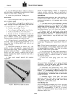
3. Clean fuel passage with ST-876 Brush or
equivalent.
Flush passages with solvent to remove
deposits.
Magnetic Crack Detection
As a precautionary measure, check cylinder head for
cracks
using ST-1166 Magnetic Crack Detector in valve and
injector port areas.
Discard head if cracked.
INSPECTION
Valve Seats
1. Check for loose
valve seat.
inserts
by lightly
tapping cylinder head near insert, if valve seat is loose
enough to bounce, mark for replacement.
A slight
looseness found only by tapping when head is cold and
covered with a film of oil is not objectionable.
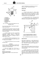
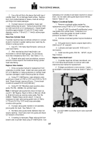
2. If seat area width (2, Fig.
2-4) exceeds 0.125
inch [3.18 mm] at any point and cannot be narrowed
sufficiently (1) during regrind, mark for replacement.
Fig.
2-4 (N10228) Valve seat insert-cross section
Injector Sleeves
Note results of pressure test.
Leaks indicate need for
replacement of injector sleeves.
Visually check sleeves,
which pass pressure test, for scratches on cup seat
area.
If seat area is scratched, mark for replacement.
Injector Tip Protrusion
Injector sleeves that have passed the above tests must
further be checked for injector tip protrusion (seat depth)
and seating pattern.
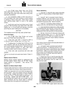
1. Lightly coat injector cup with Prussian Blue,
install injector assembly into sleeve torque to 10 to 12 ft-
lbs [1.4 to 1.7 kg m].
Remove and check seat pattern.
Bluing band must be 0.060 inch [1.52 mm] minimum in
width and located approximately 15/32 inch [11.91 mm]
from
354
ENGINE
Back to Top

