TM-5-3805-254-14-P-2 - Page 384 of 894
TRUCK SERVICE MANUAL
ENGINE
Cooling
System
The cooling system consists of engine water pump, fan
Group
8
hub, thermostats, heat exchanger, sea or raw water pump
and coolers.
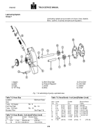
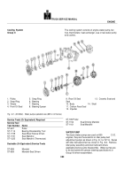
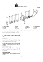
1.
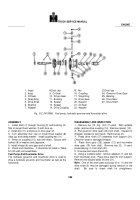
Pulley
5.
Snap Ring
2.
Snap Ring
6.
Bearing
3.
Sleeve
7.
Bearing
4.
Front Oil Seal
8.
Bearing Spacer
Fig.
8-1, (N10843).
Water pump exploded view (855 C.I.D Series)
Service Tools (Or Equivalent) Required
ServiceTool
Tool Number
Name
ST-647
Puller
ST-1114
Bearing Disassembly Tool
ST-1159
Seal-Wear Sleeve Driven
ST-1191
Seal Mandrel
ST-1225
Seal Mandrel (Thermostat)
Desirable (Or Equivalent) Service Tools
ST-658
Mandrel
ST-659
Mandrel-Seal Driven
9.
Rear Oil Seal
13.
Ceramic Seat and
Seal
10.
Body
14.
Shaft
11.
Carbon Face Seal
12.
Impeller
ST-709 Puller
ST-1154
Seal Driving Mandrel
ST-1161
Seal Mandrel
WATER PUMP
Two basic water pumps are used on 855
C.I.D.
engines, they are the eccentric or idler pulley belt
adjustment pumps as shown in Fig.
8-1 or N.T.A.
Series
with idler belt adjustment as shown in Fig.
8-2.
Remove
idler pulley assembly and drain lubricant where
applicable before pump disassembly.
Water pumps are
to be lubricated with grease meeting specifications in
Group 18 when reassembled.
380
Back to Top

