TM-5-3805-254-14-P-2 - Page 390 of 894
TRUCK SERVICE MANUAL
ENGINE
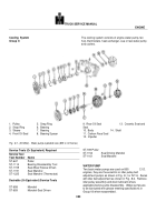
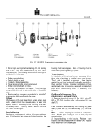
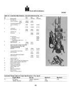
1.
linger
8.Dust Lap
I5.
Nut
23.Dust cap
2.
Keys
9.
Oil Seal
16.
Coupling
24.
Governor Drive Gear
3.
Oil Seal
10.
Driven Gear
17.
Snap Ring
25.
Bearing
4.
Snap Ring
11.
Bushing
19.
Drive Gear
26.
Drive Gear
5.
Drive Shaft
12.
Spacer
20.
Support
27.
Drive Shaft
6.
Bushing
13.
Spacer
21.
Oil Seal
7.
Adapter
14.
Drive Coupling
22.
Adapter
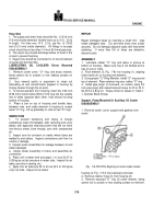
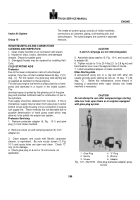
Fig.
9-2, (N10906).
Fuel pump, hydraulic governor and hourmeter drive
ASSEMBLY
1.
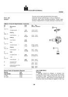
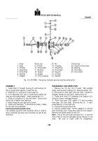
Install shaft (7) through housing (5) and bushing (4).
Slip on larger thrust washer (3) with face up.
2.
Install key (11) and press on drive gear (2).
3.
Turn assembly over; slip on small thrust washer (8)
(face up) and clamp washer.
Install coupling key (11).
4.
Press on coupling (10), hub end down.
Secure with
locknut (9) or washer and capscrew.
5.
Install slinger (6) over gear end of shaft.
6.
Check end clearance.
It should be as listed in Table
9-1(33) with unit assembled.
Fuel Pump And Hourmeter Drive
The hydraulic governor and hourmeter drive is used to
drive a hydraulic governor and hourmeter as well as the
fuel pump.
DISASSEMBLY AND INSPECTION
1.
Remove nut (15, Fig.
9-2) (if used).
With suitable
puller, remove drive coupling (14).
Remove spacer (13).
2.
Pull governor drive gear (24) from shaft.
Inspect for
chipped, cracked or worn teeth.
Remove key (2).
3.
Press drive shaft (27) assembly from support (20).
Check for wear or damaged threads.
4.
Press drive gear (26), spacer (12) and hourmeter
drive gear (19) from shaft.
Remove key (2).
If used,
press bearing (1) from shaft (27).
5.
Unscrew dust caps (8 and 23).
6.
Using a suitable puller, remove adapters (7 and 22)
from hourmeter drive.
Press drive shaft (5) from support.
Remove and discard seals (9) and (21).
Note:
One of the drive gear bushings (6 or 11) and the
drive shaft (5) may be damaged during removal of the
shaft.
Be sure to check shaft for straightness.
386
Back to Top

