TM-5-3805-254-14-P-2 - Page 395 of 894
TRUCK SERVICE MANUAL
ENGINE
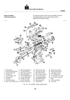
Engine Assembly
The engine assembly section covers assembly of all units
and Testing Group 14
and subassemblies to the cylinder block as well as
adjustments and engine testing.
1.
Main Bearings
10.
Water Pump/Idler Assy.
19.
Water By-Puss Tube
28.
Rear Cover Assembly
2.
Connecting Rod Bearings
11.
Fan Hub Assembly
20.
Thermostat Housing
29.
Flywheel and Housing
3.
Crankshaft and Gear
12.
Water Inlet Connections
21.
Water Manifold Assy
30.
Lubricating Oil Pump
4.
Cylinder Liner
13.
Exhaust Manifolds
22.
Rkr Lvr Hsg, Cover/Cap
31.
Vib.
Damper/Pulley
5.
Conn Rod/Piston Assy
14.
Fan Hub Mtg Brkt/Supp.
23.
Cyl Head and Gasket
32.
Cam Follower/Push Tubes
6.
Camshaft Gear
15.
Cyl Liner Pack Rings
24.
Cranking Motor/Spacer
33.
Acc Drive/Air Comp/Fuel
7.
Camshaft
16.
Cylinder Liner Shim
25.
Intake Manifold Assy
Pump
8.
Camshaft Bushings
17.
Lub Oil Cooler/Filter
26.
Main Bearing Cap
34.
Oil Pan and Gasket
9.
Gear Cvr/Trunion Bushing
18.
Rocker Levers/Shaft
27.
Cylinder Block
35.
Thermostat
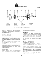
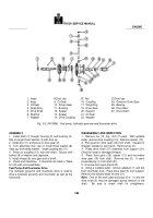
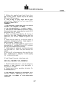
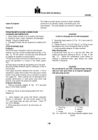
Fig.
14-1, (N 1142356).
Engine exploded view
391
Back to Top

