TM-5-3805-254-14-P-2 - Page 386 of 894
TRUCK SERVICE MANUAL
ENGINE
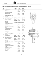
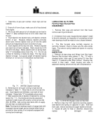
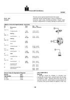
inner race, press bearing onto shaft until Inner race
bottoms on flange of shaft.
2.
Supporting bearing on outer race, press pulley onto
bearing until pulley bottoms; install snap ring in groove.
3.
Using ST-658 Mandrel, install new oil seal.
Lubricate
"O"
ring and lip of seal, position "O" ring in groove of
shaft.
4.
Install idler shaft spacer over shaft and "O" ring, press
into position through seal until spacer bottoms against
bearing inner race.
5.
Install new grease fitting, if required, fill 1/2 to 2/3 full
with grease.
See Group 18 for type grease.
6.
Position idler assembly to water pump housing.
Secure finger tight with flatwasher and nut.
Install
adjusting screw.
Do not tighten.
FAN AND FAN HUB
Check fan blades for bends, dents or cracks; clean
disassembled part as outlined in Group 0, Engine
Disassembly.
Tapered Roller Bearing Type With Bearing Spacer
DISASSEMBLY AND INSPECTION
1.
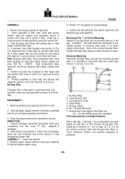
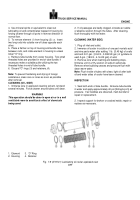
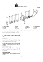
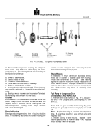
Remove pipe plugs (6, Fig.
8-4), drain oil from hub.
2.
Remove spacer (12), "0" ring retainer (10), locknut (9)
and washer (if used).
3.
Remove pulley (5) from shaft, remove front bearing
(3) and spacer (7) from pulley.
4.
Remove seal (2) and rear bearing (3), discard seal.
5.
Inspect bearings, races, and fan hub shaft for
roughness, pitting and wear.
6.
If shaft is damaged in seal mating area it can be
cleaned up by’using 240 grit or fine emery paper.
7.
Bearing races (4) may be removed with a flat punch
by striking, from the back side, alternately from side to
side until the race drops out.
8.
If bearing races are removed, inspect snap rings (8).
Do not remove snap rings unless damaged.
9.
Inspect parts for chips, cracks, wear or distorted
threads.
Replace all unserviceable parts.
ASSEMBLY
1.
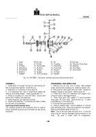
If removed, install new snap rings (8) (position into
grooves with hammer handle).
Press in bearing races
(4), beveled side out, until races "bottom" against snap
rings.
2.
Position rear bearing (3) in race (4) and press seal (2)
into pulley bore until flush.
(Lip of seal toward bearing.)
Note:
Lubricate bearings with SAE 30 lubricating oil
before installation.
3.
Coat lip of seal (2) with lubricating oil, slide shaft (1)
through seal and bearing.
Do not damage seal.
4.
Place bearing spacer (7) over shaft and install front
bearing (3).
5.
Install washer (if used) and locknut (9).
Tighten nut to
150 ft-lbs [20.7 kg m] torque.
6.
Rotate fan hub and check end clearance.
Fan hub
must rotate freely, end clearance must be 0.003 to 0.010
inch [0.08 to 0.25 mm].
7.
Place lubricated "O" ring (11) on retainer (10) and
press or drive into pulley bore.
8.
Install fan spacer (12) with cupped side next to
retainer.
9.
Position fan hub so that drain hole is horizontal, filler
hole must either be at top of hub or opposite drain hole.
Fill with grease lubricating oil to level of drain hole.
10.
Install pipe plugs, tighten to 5 to 7 ft-lbs [0.7 to 0.10
kg m] torque.
THERMOSTAT AND HOUSING
Thermostats
are not
subject to
repair, but should be
checked to make sure they are opening and closing at
the proper temperatures.
DISASSEMBLY AND INSPECTION
1.
Remove water outlet connection(s), thermostat
housing, and thermostat(s).
Remove thermostat seal
from housing.
2.
Check thermostat to see if it opens and closes at the
correct temperature.
a.
Immerse thermostat and thermometer in water.
b.
Heat water to operating temperature, allow time for
thermostat metal to stabilize with water temperature, then
compare thermostat operation with thermometer.
c.
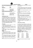
Low-range thermostats start opening at 160 deg.
F
[71 deg.
C] and are fully open at 175 deg.
F [79 deg.
C]
.
d.
Intermediate thermostats start opening at 175 deg.
F
[79 deg.
C] and are fully open at 185 deg.
F [85 deg.
C]
.
382
Back to Top

