TM-5-3805-254-14-P-2 - Page 393 of 894
TRUCK SERVICE MANUAL
ENGINE
AIR CLEANERS AND PIPING
Dry Type Servicing
1.
Disassemble cleaner.
Clean element with
compressed air.
2.
Wipe out housing with clean cloth.
3.
Inspect gasket, replace if not reusable.
4.
Install new or cleaned element.
5.
Assemble cleaner.
Heavy Duty Single And Dual Type Servicing
1.
Wipe dirt from cover and upper portion of cleaner.
2.
Disassemble cleaner and remove element.
3.
Blow out element from clean air side using
compressed air of not more than 100 psi [7 kg/sq cm].
4.
Wash element with non-sudsing detergent and warm
water.
Dry with compressed air not exceeding 40 psi [2.8
kg/sq cm].
5.
Inspect element for holes.
6.
Install new or cleaned element.
7.
Check air restriction indicator, if air restriction is
excessive, disassemble air cleaner, remove wing nut and
replace safety element.
8.
Reassemble air cleaner.
Cartridge Type Air Cleaner Servicing
1.
Disassemble cleaner.
Remove dirty Pamic cartridge
by inserting fingers in cartridge opening.
Loosen all four
corners, one at a time by pulling straight out.
2.
Clean pre-cleaner or moisture eliminator (where
applicable).
Wipe out housing with clean cloth.
3.
Inspect housing and all other parts.
Replace if
defective.
4.
It is not recommended to clean and reuse cartridge.
5.
Install a new cartridge; hold cartridge in same manner
as when removing from housing.
Insert clean cartridge
into housing; avoid hitting cartridge tubes against sealing
flange on edges of air cleaner housing.
6.
The cleaner requires ’no separate gaskets for seals;
therefore, care must be taken when inserting cartridge to
insure a proper seat within air cleaner housing.
Firmly
press all edges and corners of cartridge with fingers to
effect a positive air seal against sealing flange of
housing.
Under no circumstances should cartridge be
pounded or pressed in center to effect a seal.
7.
Assemble cleaner.
CLEANER RESTRICTION INDICATOR
1.
The restriction indicator signals when to change
cartridges.
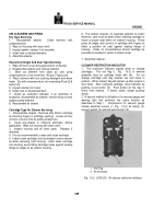
The red flag (1, Fig.
10-2) in window
gradually rises as cartridge loads with dirt.
Do not
change cartridge until flag reaches top and locks in
position.
When locked, flag will remain up after engine is
shut down.
After changing cartridge, reset indicator by
pushing re-set button (2).
Push button all the way in
firmly; then release.
If button sticks, repeat pushing
slowly.
2.
A second method is utilization of a vacuum gauge and
warning light that performs the same function as
described in Step 1.
Components for vacuum gauge
include electrical source (1, Fig.
10-3) air piping (2),
vacuum switch (3) and red warning light (4).
Back to Top

